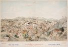
The first machine described by al-Jazari in his famous treatise of mechanics Al-Jami‘ bayn al-‘ilm wa 'l-‘amal al-nafi‘ fi sina‘at al-hiyal (A Compendium on the Theory and Useful Practice of the Mechanical Arts) is a monumental water clock known as the castle clock.

By Professor Salim T. S. Al-Hassani
Table of contents
1. Introduction
2. Clock’s Appearance
3. How it Works: Mechanism of the Castle Clock
4. Servicing and Maintenance
5. Notes on Construction
6. Appendix: Different Line Drawings and Views of the Computer Assisted Reconstruction of the Castle Clock
7. Acknowledgement
8. Bibliography and References
* * *
 |
|
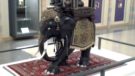
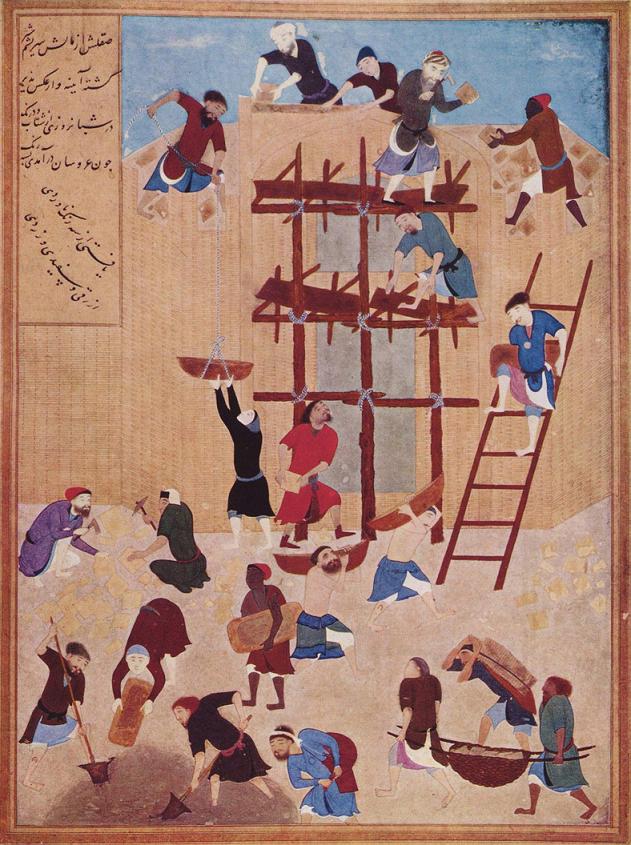
| Figure 1: Manuscript view of the castle clock. Source: Museum of Fine Arts, Boston, Egyptian manuscript, Mamluk period, Accession number: 14.533 (ink, opaque watercolor and gold on paper, 39.37 x 27.62 cm). (Source). |
The castle water clock is one of the grandest clocks mentioned in al-Jazari’s book. Details of its construction and operation have been described quite explicitly at the beginning of Al-Jami ‘ bayn al-‘ilm wa ‘l-‘amal al-nafi ‘ fi sina ‘at al-hiyal (A Compendium on the Theory and Useful Practice of the Mechanical Arts). The first chapter of Category I of the treatise devotes to this detailed description ten sections [1]. We follow in our study of al-Jazari’s device his own narrative, but our description given below is not concerned with exact details of its construction but concerned with how components are linked with each other and with the purpose of the clock and its functioning. The analysis thus provided is conceived to accompany computer animations; it is also an interpretation of the clock’s appearance to viewers and a study of its internal workings. Further, basic notes on the clock’s operating system have been provided to aid understanding of components and some are referenced to technical drawings found at the end.
2.1. What an Observer Would Have Seen During the Day
The clock has many motions throughout the day, and would have been very pleasing to watch and listen to. From the point of view of an observer, he would have seen the sun’s disc on the eastern horizon about to rise, the moon will not be seen at all and six zodiac signs are visible, while the first point of the constellation Libra is about to set.
The crescent moon would steadily be travelling from left to right on the frieze, and when in between two doors the upper door opens to reveal a figure of a man, the lower door flips round to reveal a different colour. This will occur as each solar hour of sunlight has passed. Soon after this happens, the two falcons will tilt forward and spread their wings, and a ball will drop out of their beaks and into the vase. The observer will hear a cymbal like sound, and both falcons will lean back to their original position and close their wings.
 |
|
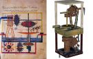
| Figure 2: View of the computer assisted reconstruction of the castle clock. |
At the point when the sixth door is about to open, the sun is at its highest altitude, and three zodiac signs have risen from the east, and three have set on the west. The crescent moon would be between the sixth and seventh doors as the sixth door opens. It is now that the musicians will begin to play their instruments. The observer would hear and see the percussionists beat their drums very lively, and a brief moment later the observer would hear the sound of the trumpets. The two falcons would still perform their duty on this hour, and it can be concluded that the clash of cymbals would have occurred together as the percussionists started to beat their drums. This would be a fair assumption judging from the distance travelled by the lead ball, and the flow of water over the water wheel.
The musicians would play at the ninth and twelfth hour. On the twelfth hour, the sun would be about to set on the western horizon, and all the zodiac signs at the start of the day would have set too. In this configuration, the zodiac disc has rotated about 180o. At this point it would have been the start of night, as the sun has set. The servant must now very quickly prepare the clock for the night ahead.
2.2. What an Observer Would Have Seen During the Night
At the beginning of night the observer would see the moon on the east horizon of the clock. Light will begin to show through the first glass roundel and the crescent moon will again be moving from the left to the right of the observer. Due to the disc with 28 holes and the lamps, the moon roundel will be illuminated such that it looks similar to the phase of the actual moon for that night.
When it is midnight, the crescent moon will be between the sixth and seventh door, and the sixth door figure will have fallen and opened the door. This will trigger the mechanism for the musicians to play, and also rotates the plate to deposit water in the second trough. It must be noted again that the bronze balls are not placed back in their slots for the night, as this could have been quite disturbing to hear clashing cymbals during the night. The musicians only play twice during the night, at midnight, and at daybreak, which coincides with the opening of the twelfth door.
When the musicians first play at midnight, the observer would see six glass roundels illuminated with light, and by daybreak all twelve roundels would have illuminated. The servant must quickly repeat the process as it did at the beginning of the day, and this is repeated throughout the days of the year.
3. How it Works: Mechanism of the Castle Clock
3.1. The Main Reservoir
 |
|
| Figure 3 |
All the power is from the main reservoir, which is an adaptation to the outflow clepsydra (Fig. 3). The float inside uses two semi-spheres of copper soldered together to form a ‘turnip-like’ shape and the reservoir uses four cylinders of copper welded together and a tap placed at its base. The two semi-spheres are sealed with wax to enable it to float, but sufficiently heavy to power the mechanics of the clock by pouring sand into it through a hole at the top. Water constantly flows out of the reservoir and the float will move down with the surface of the water. The force due to the floats’ weight is transmitted throughout the clock via ropes and pulleys.
The reservoir is filled with enough water for that day, as the hours are unequal for each day. As the float moves downwards, its linear motion is converted to angular motion and provides the means to trigger various mechanisms around the clock for users to observe the time. The flow chamber and its regulator can adjust for the unequal hours.
3.2. The Float Chamber and the Flow Regulator
 |
|
| Figure 4 |
The float chamber is placed directly below the main reservoir’s tap and will regulate the outflow from the reservoir (Fig. 4). Its purpose is to maintain a constant outflow from the main reservoir, by overcoming the always-changing head of pressure. This is done by the use of a float, which also acts as a bung for the reservoir’s tap. Due to its plug like shape, if the float is at the top of the chamber, i.e. when the chamber is full, it would stop the outflow of water from the reservoir temporarily. This chamber is an adaptation of an inflow clepsydra and also an example of a feedback system. This chamber maintains a constant head of pressure and outflow rate from the reservoir.
A flow regulator is connected to the base of the chamber, and this device allows users to change the outflow rate but still maintaining the constant head of pressure in the float chamber. Allowing the user to change the outflow rate from the main reservoir, the hours of daylight can be adjusted accordingly throughout the year. The regulator will have twelve unequal divisions (or markings) on its face to represent each sign of the zodiac. It was further sub-divided into even more divisions, and these divisions act as a guide to the positioning of the regulator for a particular day of the year. Through a process of trial and error, al-Jazari perfected his design for the castle clock.
To adjust the clock, the user would simply have to rotate the regulator so that the onyx would be in the position of the required division. The position of the onyx determines the hydraulic gradient of the flow out of the chamber. Water flows out of the onyx, and it is collected on to a ‘plate’.
3.3. Plate and Valve Trough
 |
|
| Figure 5 |
This plate is round in shape with a lip around its perimeter and is mounted on a pole, which gives it freedom of rotation about its centre. Extending from the plate is a spout approximately 0.25m in length. Water from the plate will flow out through this and is directed into a particular division of the valve trough.
The plate is rotated by the motion of the sixth, ninth, and twelfth doors. Rope is attached between these doors and a plug in the valve trough.
The trough consists of an upper and lower deck, and the upper deck is further divided into three separate compartments (Fig. 5). The upper deck is to contain the water obtained from the plate, and the three compartments correspond to the sixth, ninth, and twelfth hour doors respectively.
A plug prevents flow into the common lower deck, which earlier mentioned was connected to the figures at the back of the doors. So in the first trough, the plug would be attached to the sixth door figure, the second to the ninth, and the third to the twelfth. When these doors are released or opened, they drop the figure, and due to the lead weight attached to these figures, will pull the plug away and release the water into the lower compartment, which is common to all the other troughs.
When the plug is released, it only has restricted movement, so this will make the rope taut, and will redirect the plate to deposit its water in the next trough, i.e. the ninth hour trough and so on.
When the water is allowed to flow into the lower compartment, it will flow out of a spout and on to a small water-scoop-wheel causing it to turn.
 |
|
| Figure 6 |
3.4. The Waterwheel and The Five Musicians
The waterwheel is axially connected to a series of cams and provides motion to the musicians’ arms (Fig. 6). It is now clear that the musicians only play on the sixth, ninth, and twelfth hours of daylight. The cams are configured in a way so that the musicians play in unison a melodic tune. The cams only provide motion to the percussionists’ arms, as the two trumpeters do not move. The use of real drums has been employed to give a more authentic sound.
An over-shoot waterwheel is over a trough, and so the water is again contained. The water in the trough will flow into an air vessel that will eventually fill up. This air vessel has a siphon and also at the top is an airline that is connected to a flute. So when the vessel is filled with water, the water will start to siphon out of the vessel into a cistern. The siphoning of water occurs faster than the incoming of water, and so causes a change in pressure within the vessel. This will draw in air from the outside via a flute, and this mimics the sound of the trumpeters. This flute is placed on the wall of the clock between the two trumpeters, again to give a more authentic sound.
The cistern is the end of the power transferred by the water, and so the transmission of power from the float is now described to complete the internal motions of the clock.
3.5. The Float in the Main Reservoir
As a reminder, the float is made of two semi-spheres welded together, sealed and placed in the main reservoir. It is of sufficient weight to power the clock as it moves down with the water level of the reservoir.
A rope connects the float to the main pulley that provides motion to the rest of the clock that was not previously mentioned. Between the float and the main pulley is a small pulley that is directly above the reservoir. This is to keep the rope taut as the float moves down as the pulleys turn.
3.6. The Main Pulley and the Crescent Disc
 |
|
| Figure 7 |
There are in fact two pulleys separated by an axle of about 1 meter long (Fig. 7). The pulley that is connected to the float is at the rear of the clock, and the rope is tied to a ring in the pulley and looped around once before being tied to the float. This allows the pulley to turn relatively and proportionately to the float as it moves down.
There are two grooves in the main pulley, and the second groove provides motion to the sun, moon, and zodiac spheres that are at the top of the clock, but this will be described in more detail later.
On the other end of the axle to this pulley there is a crescent shaped disc for the revealing of light through the roundels. The disc is situated just behind the front wall of the clock behind the glass roundels.
The crescent disc has a crescent shape cut out of half its perimeter, and then an iron bar is bent to regain the shape of the disc. The purpose of the iron ring is to have the centre of gyration at the centre, and also the void will reveal a candle’s light through the roundels. A candle is placed behind the disc in such a way that during the night, the light will illuminate the roundels for people to see that one hour of solar night has passed. During the hours of sunlight, the roundels are of little use but will still be operative, because the crescent-disc provides the motion to open the doors of sunlight hours.
3.7. The Zodiac, Sun and Moon Spheres
 |
|
| Figure 8 |
The motion of the spheres is provided by a pulley connected to the rear pulley mentioned in the previous section (Fig. 8). The spheres are only simple models that mimic the sky’s motion and serve no real use, except to look very appealing and attractive.
Its operation is quite simple, but its construction is rather complicated, and has been exhaustively described by al-Jazari in section 9 of his description of the castle clock [1]. To best describe it, we mention that it has the form of a large dial with several rotating bezels to position the sun, moon and zodiac relative to each other. The rotating dial is the Zodiac, and it rotates with the pulley because it is fixed to it with bent iron bars. The rear pulley has 360 holes drilled around its perimeter, and this is for the purpose of aligning the zodiac for the day. A rope attached to a hoop in the second groove of the main pulley is connected to a nail. The rope is then wound around the groove of the spheres’ pulley once, and the nail is slotted firmly into the hole. This nail can be slotted into any of the holes in the zodiac pulley quite firmly. It provides motion to the zodiac, the sun and the moon bezels.
The middle bezel represents the sun and this can be rotated about its centre. A hole is bored into the disc, and a glass roundel is placed into this hole with a thin layer of gold on its back. During the day, the sunlight reflects on the gold layer, and it is made bright just like the sun itself.
The inner bezel represents the moon, and a hole similar to the sun but slightly smaller is bored. A clear glass roundel is placed into this hole, but the moon has an additional feature to the others. Behind the moon bezel is another bezel with twenty-eight cut-outs spaced evenly around its front face. The holes are cut in such a way that when light passes through the holes, it projects light similar to the phases of the moon. This would be seen at night, as a candle within the clock house is lit, and on-lookers will see the illuminated roundel with a phase similar to the moon of that night.
3.8. The Clock Door and Cart
 |
|
| Figure 9a |
A cart is made and a track for it to travel on is fixed near the twelve doors of solar sun hours. The cart is directly connected to the crescent-disc by a strong in-elastic string, and the crescent-disc will pull the cart as it rotates around. To ensure that the string is taut, the other end of the cart has a string that has a lead weight attached. On this cart is an arm that extends from the top of the cart to the nails on the back of the figures.
 |
|
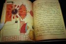
| Figure 9b-9c: The left and right figures show the upper door figure and lower door graphic, respectively. The Arabic sentence reads: “Dominions is God’s”. |
The upper sets of doors have figures with nails attached that help prompt up the doors on hooks attached to the clock wall. As the cart moves, it will travel along its track that is parallel to the twelve doors (Fig. 9a). The figure is connected to the upper doors, and as long as the figure is propped up, the door will remain closed. So the cart moves along, and will ‘knock’ the figure off its hook. The upper doors will open and the figure drops on to a catch releasing the lower doors. This happens very quickly and indicates to observers that a solar hour of sunlight has passed. Both sets of doors are configured in such a way that they favour gravity. The upper doors are tilted slightly, and will open if there is no tension in the string, and the lower doors are pivoted in the middle across its width, but is tapered larger at the top. The pictures used on the upper and lower doors can be seen in the figures 9b and 9c.
 |
| Figure 9d |
The falling of the figure triggers various other mechanisms around the clock. Each figure dropping triggers the motion of the falcons, and the musicians are triggered by the opening of the sixth, ninth and twelfth figures dropping. These are the figures that have lead weights fixed to the back to give a greater force to trigger the above mechanisms.
The cart also gives motion to the crescent-moon. The crescent-moon projects out from the cart through a slit in the front wall of the clock, and moves along the width of the clock. It is a visual guide for people to see when the next hour is coming because it moves with the cart, and thus the doors open as the crescent-moon passes each door (Fig. 9d).
3.9. The Falcons and the Vase
 |
|
| Figure 10a |
On each hour of sunlight that passes, the falcons will tilt forward, spread their wings, and release a bronze ball out of their mouth. The ball will drop onto a cymbal for all to hear. The cymbal is concealed in a vase, and also acts as a catchment for the balls (Fig. 10a).
Above the propped up figures is a piece of wood as wide as the sets of doors. Two rows of twelve slots are drilled, and a bronze ball is placed into each. There is a thin blade that prevents the ball from falling out, and the blade is connected to the figure via a slack string (Fig. 10b). When the figure falls on the hour, this string will become taut and rotate the blade such as to release two balls simultaneously. The ball drops into another channel that is common to all, and from here one ball will travel to one falcon, and the other ball to the other falcon. This is done by directing the balls from the slots to the falcons’ head via a thin copper tube.
 |
|
| Figure 10b |
The falcons are made of copper and pivoted at their feet. They are kept at a rest position so that the head is tilted back towards the clock (Fig. 10c). The wings and tail are separate and are pivoted similarly to a real falcon, and the string is attached at the ends of the wing and tail to the wall behind. When a bronze ball is in its head, the whole falcon will rotate about its perch, as if it is tilting forward. The bird will seem like it is spreading its wings and curling its tail as the strings get taut. When far enough forward, the ball drops out of the beak into the vase, creating a clashing sound. The falcon is again at an imbalance, and will return to its original position due to a counterweight attached to the perch like a cantilever with a weight at the end. Its wings and tail also return to their initial position.
3.10. The Triggering of Motion to the Musicians
 |
|
| Figure 10c |
When the sixth, ninth, and twelfth figures are released, they drop with much greater force due to a lead weight attached to its back. This has been mentioned repeatedly within the description but it must be strongly emphasized to fully understand the motions occurring. The weight must be sufficiently heavy to pull the plug from the valve trough, and also be sufficiently taut, so that the taut rope will push against the long spout of the plate, causing it to rotate and redirect its flow to the next trough. This prepares the musicians for the ninth hour, and so on. The water will then flow over the waterwheel causing it to turn, and give life to the arms of the percussionists. The flow of water after the waterwheel was described previously and details of the function of the clock shall end here.
4.1. The Servants Job for the Day Ahead
This clock would not be possible without regular maintenance, and daily set up of all the parts mentioned so far. The servant must first ensure that half a days worth of water is in the reservoir, and this is crucial for the setting up of the spheres of the zodiac. The servant must take a strong cord and tie it to the nail for the sphere’s pulley. With the zodiac positioned from the previous day, the nail is placed firmly into the hole of the pulley that corresponds to the sign that is rising from the horizon of the clock. For example, from the previous day, Aries was just about to rise from the horizon, the nail would be placed at the first point of Aries. The cord would then be wound once around the pulley and attached to a ring on the pulley directly below, i.e. the pulley for the crescent moon.
Going back to the example with Aries just about to rise from the horizon, the servant must next set the sun sphere so that it is opposite to the first point of Aries. This is done by having a firm grip of the iron bars, and turning the sun sphere by its handle. The moon is then set to the degrees of Taurus, which is the sign just after Aries. The ring with twenty-eight holes is rotated round so that the blank is behind the moon roundel. This will prevent observers from noticing the moon roundel during the day, and will rotate with the moon.
With the example of Aries, the flow regulator would be set to the point of Aries, and this would ensure that water would flow such that the hours of sun and night correspond to that particular day of the year.
Now that the zodiac, sun, moon spheres, and flow regulator are now set ready for the day ahead, the rest of the components within the clock are now placed back to their starting positions. Therefore the servant must now ensure the following:
a. The plate is directing it’s pipe to the first of three sections in the valve trough;
b. all figures are suspended on their hooks;
c. the lower doors are positioned so that the heavier end is at the top and held in place by the catch;
d. the cart and crescent moon are at the left of the clock while looking from the front;
e. the string connecting the plugs in the valve trough to the sixth and ninth doors are lifted through the angle of the cross-pipe, and the twelfth door string connects directly to the plug in the last section of the valve trough;
f. lead balls are placed in every each slot, and all the blades are in their slits.
Al-Jazari describes what should be done during the beginning of the day at sunrise [2].
4.2. The Servants Job for the Night Ahead
All the water from the reservoir should now be in the cistern, and all the lead balls collected in a container on the floor of the house. The servant must now take the water from the cistern and pour it back into the main reservoir, and the water passed through a strainer at the top. No lead balls are placed back into their slots, so the falcons will serve little purpose during the night. The cross-pipe of the plate is rotated back so that it will deposit water into the first of the valve trough partitions. The sixth door figure will be hung up, but this time the weight behind to release the plug for the musicians to play will not be hung up with it. Instead this weight is hung up with the ninth door figure, and its string is passed through the angle of the pipe. The weight for the plug in the second trough is now placed and hung up with the twelfth figure door, but its string is not passed through the angle of the pipe.
 |
|
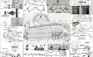
| Figure 11: Schematic chart of the castle clock. |
The servant must now put the crescent moon/cart back to its original position on the left of the clock, if looking from the front. The moon roundel must be put on to its degree for that night, and its backing ring is rotated until the appropriate moon shape is behind the roundel. The sun disc is not moved. Going back to the example with Aries, the nail from the sphere’s pulley must now be placed into the hole corresponding to the first point of Libra. The glass roundels for the hours of night should be covered, so that the crescent disc has its solid part uppermost behind the roundels.
Two lamps are now lit and placed inside the clock such that the light is spread throughout the clock. Al-Jazari describes their placing one on the left and the other on the right, so to spread light over the iron bows of the spheres. This was all the servicing that was required for the night ahead.
To conclude the description of how this clock works, a schematic chart of the clock and its components is given in Figure 11.
5.1. General Arrangement
The castle clock is quite a complex device, with lots of parts interconnected in some way to each other, and construction details are not given here, but can be found in al-Jazari’s treatise, The Book of Knowledge of Ingenious Mechanical Devices [3]. The clock described by al-Jazari suggests it should stand about 3.5m high, and 3m wide. It is not typically necessary to build a clock of such size, so there are a few factors to consider when scaling it down.
The most important part of the clock is the main reservoir and how far the main float travels within it. The amount of water held within the reservoir is not as important, because the outflow rate can be carefully adjusted using the flow regulator, but it is very important that there is sufficient water to momentarily give ‘life’ to the musicians.
As a reminder, the main float descends to its full length of travel in 12 hours, and all the connected pulleys would have rotated 180o, and the cart would have travelled the whole length of its road.
For example, if the float travels a distance x, then the cart travels a distance x too. So the circumference of the crescent disc is equal to 2x, because only half the disc is used to move the cart its full distance (see Fig. 12).
All the pulleys are of the same radius. There should be some allowance for the stretching of the ropes used, but ideally there should be none to ensure accurate time keeping.
The twelve sets of doors can now be equally spaced along the distance x, and knowing the radius of all the pulleys, the rest of the clock can be constructed relative to major components.
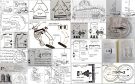
Drawings of various other components have also been included, and should be used as a guide (Fig. 13a to 13c). The dimensions given in the drawings are taken from the English translation of al-Jazari’s book. They should not be followed too accurately, as parts should be built-to-fit, and not made-to-measure.
5.2. Calibration of Time
It is not easily described, but it can be said that even al-Jazari, a great engineering mind of his time, used trial and error methods to calibrate his huge castle clock. One must painstakingly mark the flow regulator according to flow through its onyx, and the onyx is carefully filed to an appropriate size for the correct range of flows for the whole year.
6. Appendix: Different Line Drawings and Views of the Computer Assisted Reconstruction of the Castle
 |
| Figure 12: General arrangement of the castle clock. |
 |
| Figure 13a: General arrangement of the castle clock. |
 |
| Figure 13b: Crescent disc. |
 |
| Figure 14: Front View of the castle clock. |
 |
| Figure 15: Side View of the castle clock. |
 |
| Figure 16: Rear View of the castle clock. |
This research would have not been possible without the hard work of my students, especially Miss Wai Yin Chang and Mr. Jonathan W. B. Chang, who assisted in the research work for FSTC as part of their research project at the University of Manchester.
8. Bibliography and References
End Notes
[1] Al-Jazarī, The Book of Knowledge of Ingenious Mechanical Devices, op. cit., pp. 35-39.
[2] Al-Jazarī, The Book of Knowledge of Ingenious Mechanical Devices, op. cit., p. 40.
[3] Al-Jazarī, The Book of Knowledge of Ingenious Mechanical Devices, op. cit., category I, chapter 1, sections 1-10, pp. 17-41.
[4] Al-Jazarī, The Book of Knowledge of Ingenious Mechanical Devices: Kitâb fî ma’rifat al-hiyal al-handasiyya, English translation and introductions by Donald R.. Hill, Dordrecht: D. Reidel, 1974, pp. 17-41.
Discover the golden
age of Muslim civilisation.
© Copyright FSTC Ltd 2002-2020. All Rights Reserved.