Five pumps or water-raising machines are described by al-Jazari in his monumental treatise of mechanics Al-Jami' bayn al-‘ilm wa 'l-‘amal al-nafi' fi sina'at al-hiyal (A Compendium on the Theory and Useful Practice of the Mechanical Arts). The following long article is a detailed study of the third of these water-raising devices. The study presents a detailed analysis of the mathematical and mechanical principles of this sophisticated machine and explains its functioning. Further, the various components of the pump are reconstructed via computer assisted design. A profusion of 3D graphics and 3D animations show the device in different angles and helps in viewing it in operational mode.
Table of contents
1. Preface: Summary and Objectives of this Research
I. Characterisation of the tradition of Islamic Technology
1. Beginning of Islamic Science and Technology
2. Islamic Technology
3. The Teaching of Islamic Engineering
4. Comparison of Islamic and Modern Engineering Concept
5. Transmission of Islamic Studies
II. Al-Jazari: Outline of his Biography and of his Work’s Historical Context
1. Al-Jazari’s Life and Personality
2.1. Why is Al-Jazari’s Work so Important?
2.2. Why was there so Limited Works by other Scholars?
III. Water-Raising Devices: History and Technical Principles
1. What Led to the Development of Water Raising Devices?
2. Ancient Water Raising Devices
2.1. The Shaduf
2.2. The Archimedean Screw or Water-Snail
2.3. The Noria
2.4. The Saqiya
IV. Al-Jazari’s Third Water-Raising Device
1. A Revolutionary Idea
2. Description of the Device
3. Possible Problems Encountered
V. Research and Analysis
1. Scoop-Wheel or Water Turbine
1.1. How did al-Jazari Invent the Scoop-Wheel Design?
1.2. Why did he Use the Scoop-Wheel Instead of the More Common Overshot Wheel?
1.3. Why did he Convert the Undershot Scoop-Wheel to an Overshot Scoop-Wheel?
1.4. Comparison between the Undershot Wheel and the Overshot Wheel?
1.5. John Smeaton Experiment
2. Cogwheel and Lantern Pinion Gears
3. Analytical Interpretation of the Gears Found on al-Jazari’s Illustration
3.1. Why is it Elliptical in Shape?
3.2. Why do the Gears have Sharpened Teeth?
3.3. Possible Relationship to the Saqiya Gears
3.4. What did the Actual Gears Look Like?
3.5. Will the selected Gears be able to Transmit High Torque?
3.6. What are the Methods Used to Enhance its Efficiency?
4. Sindi Wheel
4.1. Possible Problems Encountered?
4.2. What are the Methods Used to Enhance its Efficiency?
5. Where Does Water from the Lower Chamber Flow?
5.1. Possibility 1
5.2. Possibility 2
5.3. Possibility 3
6. Rudimentary Components and Materials Used by Al-Jazari
6.1. Bearings
6.2. Axle
6.3. Lubrication
6.4. Pipes
6.5. Fittings
6.6. Materials
6.7. Jackwork or Jack Figures
7. Weights and Measurements
VI. Mathematical Analysis
1. Analysis of the Total Head of Water Jet
2. Analysis of the System of the Third Water Raising Device
3. Assumptions and Considerations
3.1. Deflection Angle for the Bucket
3.2. Maximum Weight Of Water Being Raised
VII. 3D Graphics and Animations
1. Identification of Parts
VIII. Conclusion
IX. References
1. General
2. References for Mathematical Analysis
***
The following study investigates an ancient water-raising device invented in the 13th century by an Islamic inventor and engineer, al-Jazari. This invention is known as the Third Water Raising Device, which is found in the important treatise of al-Jazari’s Kitab ma‘rifat al-hiyal al-handasiya (The Book of Knowledge of Ingenious Devices) [1]. We explore hereinafter thoroughly the origin and genius of the inventor, al-Jazari, and his invention, with in-depth research and discussion from the evolution of the invention to the rudimentary components used.
The study is composed of 7 chapters and 12 appendixes (which can be navigated by using the Table of Contents above). In addition, mathematical analysis and 3D animations of the system are also included to further aid the reader in understanding the concept of the invention.
Chapter I introduces a brief history of technology in Muslim heritage. The scope of interest is focused on the various branches of Islamic technology, its educational system and the possible transfer of knowledge to the West. A comparison of Islamic and modern engineering concepts is also investigated.
In Chapter II, the life and environment of the inventor, al-Jazari, and his factors of innovation are investigated. All of which contributed to the compilation of his important work, The Book of Knowledge of Ingenious Devices. The importance of al-Jazari’s work as an engineering document is attributed to the various ingenious components and concepts included, most of which are of relevance and are used in modern-day engineering.
In Chapter III, the origin and development of the ancient water-raising devices are summarised. These devices were invented as early as 2500 BCE and were driven by either animal or water power. The relevance of some of these designs to al-Jazari’s invention is discussed in Chapter V.
In Chapter IV, the evolution of the inventions is discussed, followed by a description of the system of the inventions. The possible problems that might be encountered during its operation are also discussed. The technical and mechanical aspects of the inventions are discussed in Chapter V.
In Chapter V, components ranging from the large scoop wheel to the rudimentary bearings that al-Jazari used are investigated and discussed. References are made to relevant components of the ancient water-raising devices. The materials available and unit scales, which he used to define measurements, are also discussed.
In Chapter VI, the mathematical analysis of the system of the invention is derived and discussed. The formulas derived have been programmed into a Microsoft Excel program to estimate the head of the water jet, the force capable of raising the water and the weight of the water raised.
In Chapter VII, 3D graphics and animations are constructed, using 3D Studio Max R3.1, based on the findings of the research and mathematical analysis done. The 3D animations consist of a 360° rotational view movie file and another one that shows the movement of individual components during its operation.

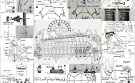
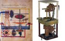
Figure 1: Picture of the pump for raising water of al-Jazari, preserved in the manuscript copy held in Topkapi Sarayi Library, Ahmet III collection, MS 3472 [2]
However, despite all the research undertaken in the last decades, the field of Islamic technology is still under-investigated. In this regard, Donald Hill declares: “As far as I am aware, there has been no archaeological study of medieval Islamic technology, nor any detailed technical examination of those machines, which still exists, such as the noria at Hamat, Syria.”
Our aim in this study is to contribute to this investigation by analysing al-Jazari’s Third Water-Raising Device, showing the technological innovation represented by the invention of this machine. One of our main tools in that will be to rely on the construction of 3D graphics and animations as visual aids for a better understanding of the device.
This work was carried out by undertaking the following tasks:
Research into technology in Muslim heritage;
Research into al-Jazari’s life, environment and work;
Research into the development of the water-raising devices;
Analysis of al-Jazari’s Third Water-Raising Device;
Analysis of the innovation of the invention of this machine;
Analysis of the technical aspects of the invention;
Analysis of the mechanical aspects of the invention.
Mathematical analysis of the invention;
Construction of 3D graphics and animation;
Evaluation.
[1] The treatise survived under another title: Al-Jāmi‘ bayn ‘l-‘ilm wa ‘l-‘amal al nāfi‘ fī sinā‘at al-hiyal,. [A Compendium On The Theory And Practice Of The Mechanical Arts]. For more details, see FSTC, 800 Years Later: In Memory of Al-Jazari, A Genius Mechanical Engineer.
[2] Even though the machinery in the lower level was hidden from viewers and the cow was a wooden dummy, the pump was an entirely automatic design, powered either by the water turbine in the lower level, the upper horizontal axle drove the sindi wheel carrying the yellow belt with its attached water-pots to lift water to the upper level.
[3] For more details, see Appendix 1.
The tradition of Islamic science and technology had its roots in the Hellenistic Greek civilisation, whose main centre was at Alexandria. Greek civilisation in turn has been nourished by the earlier cultures of the Near East and the Mediterranean. However the real beginning of Islamic science did not occur until the start of the 3rd century AH/ 9th century CE, nearly two hundred years after the beginning of Islam.
The reasons for this interval were the conquests to the territorial limits with the addition of the Iberian Peninsula and Central Asia, during which the Muslim faith became predominant. Followed by the completion of the codification of the Arabic language made it available to all educated Muslims as a vehicle for the expression of literary and scientific ideas [1].
Islamic science flourished during the Golden Age, a period of unrivalled intellectual activity, whereby Muslim scholars made important and original contributions in all fields; namely literature, science and technology. This blossoming was the result of the increasing quality of material life in Muslim cities and the faith in Islam as the driving force.
At the same time, the urban life of these Muslim cities, the material prosperity, the varied local industries, and the local and international trade would not have flourished without developing technology [2]. Important advances in agriculture were also made in the Golden Age where ancient networks of wells, qanat (underground canals), waterwheels and water-raising devices were preserved and improved.
It is interesting to note that the technology they dealt with was one which utilised natural forces within the environment in question, making the maximum use of human skills and causing the minimum amount of disturbance within the natural environment [3].
Furthermore, Islamic technology had the means then to make complicated machines (as what modern technology had developed during the past two centuries), however, the Muslims never took that step which would mean the creation of technology out of harmony with the natural environment. Feeling instinctively the dangers of the development of technology, which incorporates elements alien to the natural environment resulting in the loss of nature equilibrium.
This sentiment is reflected by the 15th century Persian Sufi poet ‘Abu al-Rahman Jami who seemed to have a presentiment of the present-day predicament of man, who in his attempt to gain knowledge has lost sight of the spiritual empyrean. As in one of his quatrains, he says [4]:
Scientific research and development began to decline in the 12th to 13th century CE. The reasons are complex but the most obvious ones were the simultaneous Spanish Catholic and Mongol invasions which devastated the organic infrastructure of the Eastern and Western parts of the Muslim world.
There are many branches of Islamic studies, whereby only the subject of relevance, Islamic technology, will be studied hereafter. Islamic technology can be further divided into two categories; namely Fine Technology and Utilitarian Technology [5].
Fine technology refers to machines or instruments that were designed to cause wonder and aesthetic pleasure to courtly circles, for timekeeping, or for the use of scientists (mainly astronomers). The source of information on fine technology can be found in a few precious technical treatises, such as al-Jazari’s ‘The Book of Knowledge of Ingenious Mechanical Devices’.
Utilitarian technology, however, refers to machines that were essential to the economic prosperity of society but were very much simpler technically than the construction of Fine Technology. The source of information on Utilitarian Technology comes largely from archaeology finds, examination of existing machines and references in the works of geographers, travellers and other non-technical writers. Machines of this category are mills, water-raising devices and textile machinery [6].
It is interesting to note that al-Jazari’s Third Water-Raising Device incorporates the two categories of technology together, as the machine is designed to be a beautiful ornamental artefact with splendid craftsmanship, and raises water at the same time.
Many Muslim scholars devoted themselves to the study of the laws of simple machines, basing themselves on the teaching of Archimedean, Alexandria and the pseudo-Aristotelian schools, the latter associated with the Mechanica (see Fig. 2).

Figure 2. A miniature depicting a traditional scene of instruction.
They also knew the Book of Mechanica by Hero of Alexandria and the Book of Pneumatica by Philo of Byzantium. These and other Greek and Alexandria works served as a basis for their research in this domain [7].
The Alexandria school teaches a series of writings on various mechanical devices, gadgets and automata. This branch of science is called the ‘ilm al-hiyal’ in Arabic and has attracted the imagination of Muslims, fascinated with the unusual, ‘ilm al-hiyal’ itself has always been related in the Muslim mind to the occult sciences and magic, as the word itself whose roots means stratagem or ruse, shows.
In addition, many Muslim scholars also learn from the works of their predecessors. In accordance, a series of works describing complicated machines and gadgets can be found in various important works. From the treatise of the Banu Musa on the balance ‘qarastun‘, those attributed to Ibn Sina such as the ‘Mi‘yar al‘uqul‘ (The Standard of the Intelligence), to the work of the 13th century AD author Ibn al-Sa‘ati who describe the clock of Damascus [8].
Another important feature of the thinking behind many of the devices described in the treatises is the preoccupation of the Arab engineers with controls, particularly with controls that would allow a given machine to continue working for a long period of time without human intervention [9].
The above-mentioned might also be the basis of teaching for al-Jazari and he, in turn, will also contribute to this method of teaching through his work, ‘Kitab fi ma‘rifat al-hiyal al-handasiya’ (The Book of Knowledge of Ingenious Mechanical Devices).
The Book of Knowledge of Ingenious Mechanical Devices is a compilation of writing on automata and the like, which were a source of wonder and served as pastimes for princes and rulers. It consists of six parts, fifty complicated mechanical devices such as clepsydras and fountains, some of practical use and others more for amusement, following the tradition of the Alexandrines. The treatise was translated from Arabic into Persian as late as the 19th century and because of the variety of its content and beautifully illustrated manuscripts found in relative profusion, has become the best-known work of its kind in the West after it had been studied by historians of science and of art since the 19th century [10].
There are a few areas whereby there is a notable difference between Islamic and modern engineering concepts, namely in what concerns the use of mathematical analysis, the lack of sufficient resources and the use of various sources of power. These are further elaborated as follows.
4.1. Calculation (Mathematical Analysis)
The assumption for the Modern Engineering Concept is that engineering tasks must be accompanied by rigorous mathematical analysis. Whereas in the Islamic Engineering Concept of the past, most of the mathematical relationships that underlie the physical phenomena had not been identified, and engineers had to draw upon a large fund of practical experience. This is to say that the Muslim engineers of antiquity most probably didn’t do many calculations at all and obtain the best results through trial and error methods.
Of course, not all the work of Muslim engineers was so laborious; they had a clear understanding of arithmetic, plane geometry, and measurement, and they used these sciences to the full in the construction and assembly of their devices. But when a set of mechanisms was particularly complex and delicate, final assembly and adjustment were done by painstaking trial and error [11].
4.2. Limited Resources
The Muslim engineers most probably needed to have at their command all the contemporary scientific and technical skills available in order to obtain the best possible results from the limited resources at their disposal.
4.3. Source of Power
Modern Engineering uses fossil fuel, water pressure, air pressure, nuclear energy etc. for its source of power whereas Islamic Engineering was essentially based only upon the use of the effects of water pressure and air pressure.
5. Transmission of Islamic Studies
Islamic Studies obtained most of its knowledge from various ancient civilisations (see Fig. 3), and subsequently, the transmission of knowledge from Islamic Studies to Europe was mainly by literary means and occurred on a large scale. However, the situation is completely different for Islamic Engineering, there are very few works in Arabic dealing with engineering, and the treatises that have survived were never translated into Latin nor, until recent times, into any modern European language.

Figure 3. A scheme depicting the transmission of science and learning from the civilisations of Antiquity to the Islamic world.
Therefore, we cannot always assume that diffusions came from Islam into Europe simply because the constructions appeared earlier in Islam. The construction might have appeared in the same source of reference/ideas that may have come from the classical world; eg. Philo of Byzantium, when craftsmen examined the constructions of their predecessors and we must never dismiss the possibility that the invention occurs independently in different cultural areas.
Not surprisingly, in view of the foregoing, investigations into the transfer of Islamic Engineering seldom arrive at firm conclusions. Nevertheless, informed speculation should continue until fresh light can be thrown upon diffusions by new discoveries in literature, iconography or archaeology. In the process, some questions may ultimately be resolved, others moved closer to resolution. Whereas for the time being, we can summarise the present state of knowledge in some of the more important engineering subjects; eg. the water-raising machine [12].
There is no evidence for al-Jazari’s water-raising machines or the ideas embodied in them having been transmitted to Europe. In particular, the crank in his fourth machine, and the fifth machine as a whole, with its conversion of rotary to reciprocating motion, its true suction pipes and its use of the double-acting principle, all these could have been of great importance in the history of machine design. Oddly enough, when the European piston pump makes its appearance in the fifteen-century writings of Taccola (1450) and Martini (1475) the suction stage is already incorporated. Indeed it predominates, in that the forced or delivery stage of the pumps’ action is little more than the stroke of the piston. It is very unlikely that either of the two engineers in question had any knowledge of al-Jazari’s work. Further research may one day identify the sources of the new machines [13].
It is important, however, not to evaluate Islamic engineering only with regard to its contribution to the development of its European counterpart. Engineers in the Islamic world were responding to the needs of society and in a number of fields, for example, irrigation, masonry construction and milling, their responses were conspicuously successful [14].
[1] Ahmad Y. al-Hassan & Donald R. Hill, Islamic Technology: An Illustrated History. Cambridge. Paris/Cambridge: UNESCO/ Cambridge University Press, 1986, p. 19.
[2] Ibid, p. 8.
[3] Ibid, p. 147.
[4] S. H. Nasr, Islamic Science: An Illustrated Study. Photographs By Roland Michaud. London: The World of Islam Festival Trust, 1976, pp.147-150.
[5] L. Sprague De Camp, The Ancient Engineers. Garden City, N.Y.: Doubleday, 1963, p. 283.
[6] Dionisius A. Agius & Richard Hitchcock (editors), The Arab Influence in Medieval Europe: Folia Scholastica Mediterranea. Ithaca Press, 1994, p. 25.
[7] S. H. Nasr, Islamic Science: An Illustrated Study, op. cit., p. 144.
[8] Ibid, p. 145.
[9] D. A. Agius & R. Hitchcock (editors), The Arab Influence in Medieval Europe, op. cit., p. 30.
[10] S. H. Nasr, Islamic Science: An Illustrated Study, op. cit., p. 145.
[11] John R. Hayes (editor), The Genius of Arab Civilization Source of Renaissance. Oxford: Phaidon Press, 1976, p. 180.
[12] Donald R. Hill,Islamic Science and Engineering. Edinburgh: Edinburgh University Press, 1993, pp. 226-227.
[13] Ibid, pp. 228-229.
[14] Ibid, p. 235.
Al-Jazari was in the service of Nasir al-Din, the Artuqid King of Diyar Bakr. He spent twenty-five years with the family, having served the father and brother of Nasir al-Din. The Artuqids were a Turcoman Dynasty who maintained a precarious autonomy during the twelfth century in Mesopotamia. By 1811, however, they became vassals of Saladin [2]. It can be assumed that conditions during this period were fairly quiet and allowed al-Jazari to pursue his vocation in peace.
He received patronage from the Artuqid Kings and financial means were provided through salary and pension. Therefore he was able to devote all his time to study, research, writing and inventions [3].
Al-Jazari was quite evidently a master craftsman himself [4], and regarded himself as in a succession of craftsmen and engineers [5]. He states this point, by describing in scrupulous detail how each device was constructed [6], and through the language that he used, which were terms common among the craftsmen of that time, many of which are in use up to the present day [7].
Furthermore, he expressed awareness of the need to develop machines with a better design and greater output than the traditional ones. However, he does not like to copy his predecessors’ work blindly, rather concerned with only innovative and ingenious designs/inventions [8].
Al-Jazari’s main virtues were the ability to carefully manufacture and assemble components, and devise real improvements on the work of his predecessors. His main faults was a tendency to be inconsistent in his dimensions, some vagueness about the positioning of the equipment [9], and his inability to give a coherent record of the mathematical or geometrical process [10].
Nevertheless, taking drawings and text together, it can be said that he fulfilled his declared intention of describing the devices so that they could be reconstructed by a successor. Indeed, the “castle” water clock was reconstructed in the Science Museum, London, for the 1976 World of Islam Festival. It works perfectly, exactly in accordance with al-Jazari’s intention [11].
2. Al-Jazari’s Work: The Book of Knowledge of Ingenious Devices
2.1. Why is Al-Jazari’s Work so Important?
Until modern times there is no other document like Al-Jazari’s, from any cultural area, that provides a comparable wealth of instructions for the design, manufacture and assembly of machines [12] with a description of scrupulous detail on how each device was constructed and with beautiful illustrations. In accordance, based on al-Jazari’s work, a present-day craftsman can construct a device from the book with relative ease and the device would work in accordance with al-Jazari’s intention. One such example is the ‘castle’ water clock that was reconstructed in the Science Museum, London, for the 1976 World of Islam Festival [13].
However, Al-Jazari hesitated about first writing his book for fear of adverse criticism. According to him, he finally composed his treatise in obedience to his master’s command, Nasīr al-Dīn Mahmū ibn Muhammad (r. 597-619 H/ 1200-1222), ruler of the Turkish Artuqid dynasty which ruled across eastern Anatolia [14]. We therefore owe a great deal to this prince for our possession of a unique document. We rely so heavily upon al-Jazari for information about Arab mechanical technology that it would be only too easy to lose a sense of perspective [15].
2.2. Why was there so Limited Works by other Scholars?
No doubt this is partly due to the fact that there was usually a social and cultural divide between those who created and those who wrote. When a scholar described a machine that had been constructed by an illiterate craftsman he was usually interested mainly in the finished product; he neither understood nor cared about the messy business of construction.
A secondary factor was that a craftsman even when literate might have been reluctant to impart his knowledge to potential competitors, preferring to pass it on to his sons by word of mouth.
After all, over three centuries separate al-Jazari (who died in 602 H /1206) from the Banu Musa (236 H/850) and we know from the Mafatih and other pieces of evidence that the intervening period was in no way sterile and undoubtedly witnessed the flourishing of mechanical arts, wherever and whenever conditions were favourable [16].
[1] For more details on al-Jazari’s life, environment and the historical context of his work, see below Appendixes 3-5.
[2] D. R. Hill, Studies in Medieval Islamic Technology. From Philo to al-Jazari-From Alexandria to Diyar Bakr. Edited by David A. King. (Variorum Collected Studies Series). Aldershot, Eng. /Brookfield, Vt.: Ashgate, 1998, Category XV, p. 253.
[3] A. Y. al-Hassan & D. R. Hill, Islamic Technology, op. cit., p. 12.
[4] J. R. Hayes (editor), The Genius of Arab Civilization Source of Renaissance, op. cit., p. 177.
[5] D. R. Hill, Studies In Medieval Islamic Technology, op. cit., Category I, p. 22.
[6] J. R. Hayes (editor), The Genius of Arab Civilization Source of Renaissance, op. cit., p. 177.
[7] A. Y. al-Hassan & D. R. Hill, Islamic Technology, op. cit., p. 10.
[8] See Appendix 2.
[9] D. R. Hill, Studies In Medieval Islamic Technology, op. cit., Category XV, pp. 254-255.
[10] Al-Jazari, The Book of Knowledge of Ingenious Mechanical Devices. Translated and Annotated by Donald R. Hill. Dordrecht: D. Reidel, 1974, Devices, Part III, p. 279.
[11] D. R. Hill, Studies In Medieval Islamic Technology, op. cit., Category XV, pp. 254-255.
[12] Ibid, Category II, p. 224.
[13] Ibid, Category XV, pp. 254-255.
[14] See Appendix 4.
[15] D. R. Hill, Studies In Medieval Islamic Technology, op. cit., Category II, p. 224.
[16] Ibidem.
The supply of water for irrigation, drinking, domestic and industrial purposes has always been a vital consideration in Muslim land, considering the climatic and topographical conditions [1]. Even though water is available, another problem would be to find ways to raise water from various sources for the needs of men, thus leading to the development of various water-raising devices for this purpose [2]. Subsequently, the question of which water-raising machine to use is affected by various factors, such as the nature of the source of the water, the height of the lift, the type of constructional materials available and the quantity of water required [3].
In addition, the rise of Islam triggered the agricultural revolution to meet the needs of the growing Muslim population [4]. An important aspect of this revolution was that it was accompanied by a complete review of the whole irrigation system since the pre-Islamic irrigation systems were deemed inadequate to meet the needs of the new agriculture revolution. Therefore leads to another phase in the development of technology for canals, water-raising devices and methods for storing, conveying and distributing water [5].
It had been said:
“So great was the progress made that it would only be a slight exaggeration to claim that by the eleventh century AD, there was hardly a river, stream, oasis, spring, known aquifer or predictable flood that went unused.”[6]
2.1. The Shaduf
The most ancient water-raising device is the shaduf, illustrated as early as 2500 BCE in Akkadian relief and about 2000 BC in Egypt [8], and is still in use today in many parts of the Middle East. Its success is due to its simplicity and its efficiency whereby, a bucket of water is raised from a well or stream by means of a counterweighted lever (see Fig. 4).

Figure 4.Two shadufs were used to raise water from a river in Egypt.
When it is necessary to raise water to a considerable/greater height, then a series of shadufs is erected in a line on a gradient leading from the source to the discharge point. The device nearest to the source discharges water into a tank, whence it is extracted by the second, and so on [9].
2.2. The Archimedean Screw or Water-Snail
The Archimedean Screw or Water-Snail was probably invented by Archimedes, its origin are datable to about 250 B.C. and by Roman times it was widely used [10]. It consists of a helical wooden blade rotating within a barrel-like wooden cylinder with the lower end of the screw dipping into the water source while the upper end discharges into an irrigation ditch. The angle of the screw therefore determines its water output (see Fig. 5).
However, unlike the Shaduf, the device has not retained its popularity although it was still in common use in Upper

Figure 5. An Archimedean Screw being used to raise water in Egypt’s Nile delta to irrigate a field. Photograph by Helen and Frank Schreider of the National Geographic. (Source)
Egypt and other parts of the Arab world in 1965 but had since disappeared from the Delta region [11].
2.3. The Noria

Figure 6. A giant Noria Wheel at Hama, Syria.
The Noria, which is driven by waterpower, probably originated in Syria or al-Jazira about 200 BC [12], with a description by Vitruvius (100 BCE) and by Roman times it was widely used. The Noria is self-acting, therefore its operation does not require the presence of either man or animal. It is considered the most facile and advantageous way of raising water in great quantity to any altitude within the diameter of the wheel, wherever there is any current of water to continue its motion [13]. However it could be made quite large, therefore it is expensive to build and maintain.
It consists of a large wheel; fitted with a series of compartments that dip into the water and scoops up water, as the wheel rotates as it is driven by the velocity of the current. The water is then discharged into a head tank or an aqueduct at the top of the wheel.
The well-known wheels at Hama on the river Orontes in Syria have a diameter of about 20 meters (see Fig 6).
2.4. The Saqiya

Figure 7. A Saqiya at Babraki, Pakistan. Water is being discharged from the pot garland into a trough leading to a channel on the left.
The Saqiya, which is driven by animal power, was almost certainly invented in Egypt in the third century BC [14], and was known by Roman times, from about the start of the Christian era. It is probably the most widespread and useful of all the water-raising machines that medieval Islam inherited and improved (see Fig 7).
It consists of a chain-of-pots or pot garland, driven through a pair of gears by an animal moving in a circle. The animal pushes a drawbar through the circle, turning an axle whose pinion meshes with a cogwheel gear. This gear then turns the chain-of-pots, which consists of suspended earthenware pots between two ropes, carrying water. The chain-of-pots is optimal for raising comparatively small amounts of water from comparatively deep wells [15].
[1] A. Y. al-Hassan & D. R. Hill, Islamic Technology, op. cit., p. 37.
[2] See Appendix 6.
[3] D. R. Hill, A History of Engineering in Classical and Medieval Times. London/New York: Routledge, 1984, p. 145.
[4] See Appendix 7.
[5] A. Y. al-Hassan & D. R. Hill, Islamic Technology, op. cit., pp. 206-207. See also Appendix 7.
[6] Ibid.
[7] Detailed explanations of the parts and working principles of the ancient water-raising devices are given in Appendix 8.
[8] D. R. Hill, Islamic Science and Engineering, op. cit., p. 92.
[9] A. Y. al-Hassan & D. R. Hill, Islamic Technology, op. cit., p. 38. See also The Shaduf Project: A European Commission Report on Mediterranean Shaduf Use and History.
[10] Norman Smith, Man And Water: A. History of Hydro-Technology. London: Peter Davies, 1976, p. 12.
[11] D. R. Hill, Islamic Science and Engineering, op. cit., pp. 92-93.
[12] D. R. Hill, Studies In Medieval Islamic Technology, op. cit., Category I, p. 13.
[13] Jal Dastur Cursetji Pavry (editor), Oriental Studies in Honour of Cursetji Erachji Pavry. London: Oxford University Press, 1933, p. 238.
[14] D. R. Hill, Studies In Medieval Islamic Technology, op. cit., Category I, p. 13.
[15] D. R. Hill, A History of Engineering in Classical and Medieval Times, op. cit., pp. 138-139.
There was obviously a demand from al-Jazari’s masters for devices that would provide amusement and aesthetic pleasure, but it is also highly likely that his responsibilities included the design and construction of public works. In this capacity, he would have appreciated the need for improving the efficiency of water-raising methods, and have attempted to devise means to this end. Apart from their potential as practical machines, his designs have the added significance of incorporating techniques and components that are of importance in the development of Islamic technology [1].
Therefore, al-Jazari tinkered with the idea of a fanciful water-raising device, which pictured a fake ox that appeared to provide a wheel with motive force but was in fact supplied by a hidden current of waterpower driving a water turbine [2].

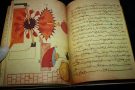
Figure 8. Another depiction of al-Jazari’s pump for raising water is in a copy manuscript held in Topkapi Sarayi Libray in Istanbul. (Source).
The Third Water-Raising Device was intended as a decorative attraction near an ornamental lake [4], with an element of mystification about it. Thence an ornamental lake erects an elegant open structure, with only its automata working parts visible to spectators, thus leaving the spectators curious on how the device is powered (see Fig. 8).
Considering the nature of al-Jazari’s working environment, it is most likely erected in the King’s garden, where it caused wonder and aesthetic pleasure to courtly circles and raised water for irrigation to the garden at the same time.
It was, however, simply an elegant development of a utilitarian device that was used for supplying water for irrigation and domestic purposes. Development of the Saqiya, having the main difference of the device being powered by water power instead of animal power.
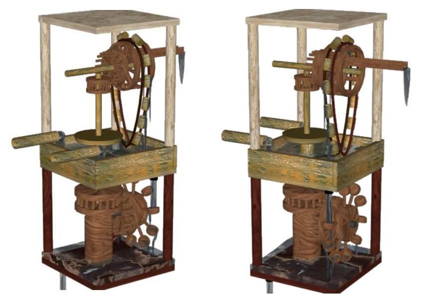
The structure itself is quite small, being divided into 2 sections; the lower chamber where the water-driven mechanism is ‘hidden’ under the ground and the upper chamber whereby the automated mechanism above the pool is made visible.
It consists of a copper pool with an escapement, whereby water flows into the lower chamber and drives the Scoop-Wheel. The rotating Scoop-Wheel in turn rotates the Cogwheel and Lantern Pinion gears, driving the vertical hollow copper pillar with an iron stanchion beneath it. The rotating pillar in turn rotates the second set of gears in the upper chamber, driving the Sindi Wheel that raises water to the head tank (this is seen in Fig 8 and in the reconstructed depiction in Fig. 9) [5].

Figure 9. A 3D graphic showing the flow of water when the device is working.
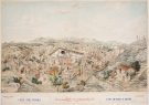
Initially, it was thought that this device was simply an unrealistic idea of al-Jazari, whereas in fact, the Third Water-Raising Device is a scaled-down version of a utilitarian machine [6]. A similar large-scale version of this machine can be located on the River Yazid in Damascus, on a riverside path called the ‘Land of the Norias’ (because of the number of Norias and mills that used to line it) (see Fig. 10 and 11). The working principles are the same, however, the mechanisms are orientated differently and some of the mechanisms are made differently; for example, the Scoop-Wheel is replaced by an Undershot-Wheel, and the pot garland is made of chains and metal buckets.

Figure 10: Restored paddle wheels driven device on the river Yazid, Damascus, dating from the 13th century CE. It is very similar to al-Jazari’s Third Water-Raising Device.
***

Figure 11. This drawing is based on the working principles of al-Jazari’s Third Water-Raising Device.
One serious mechanical problem is the possibility of slippage of the ropes and earthenware pots, around the axle of the Sindi Wheel [7]. This could result in reduced overall efficiency as it takes longer time for the earthenware pots to reach the top and pour their content into the head tank.
A solution would be to reduce the weight of the water being lifted at any one time, in relation to the total weight of the rope and earthenware pots. However, this would also result in reduced overall efficiency.
However, a better solution would be the use of a set of headless nails, driven into the axle at the appropriate spacing [8], that will support the base of the pots as it travel around the axle of the Sindi Wheel, thus preventing slippage.
The other problems faced would be the high cost of installing and running such machinery, and the small output that would only irrigate a small area. Lastly, justifications for the need to raise a comparatively small amount of water from a running stream to a high head.
The best solution would be that the King who wanted a fanciful water-raising device commissioned the device so as to cause wonder and aesthetic pleasure to courtly circles.
[1] D. R. Hill, Islamic Science and Engineering, op. cit., p. 97.
[2] Thomas F. Glick, Islamic And Christian Spain in The Early Middle Ages. Princeton: Princeton University Press, 1979, p. 238.
[3] For al-Jazari’s detailed description on the design, working principle and materials used for this device, see Appendix 9.
[4] J. R. Hayes (editor), The Genius of Arab Civilization Source of Renaissance, op. cit., p. 182.
[5] More details of the working of al-Jazari’s machine are given in Appendix 10.
[6] D. R. Hill, A History of Engineering in Classical and Medieval Times, op. cit., p. 148.
[7] See Chapter V, section 3: Sindi Wheel.
[8] J. G. Landels, Engineering in the Ancient World. London: Chatto and Windus, 1980, pp. 71-72.
Most of the ancient water-raising devices have been described in the works of classical and medieval writers, and several types can still be seen serving their purposes today. It is rather more difficult to assess their capabilities since there does not appear to have been any systematic study of their characteristics in terms of power, efficiency, discharge rate, and so on.
The early writers, in rare comments on such matters, are unreliable. This is no fault of theirs but is due to our inability to assign exact modern quantities to the measures that they used. Some attempts have to be made, however, since knowledge of a given machine’s characteristics can help to explain why it was chosen to meet a certain set of needs [1].
Hence the question of which machine to use is affected by various factors; the nature of the source of water, the required height of the lift, the type of constructional materials available [2] and the quantity of water required.
The table below could be used to find the suitable water-raising device, it consists of an average figure of the output of the various water-raising devices. Note that the figures for the areas that could be irrigated by each machine are derived from Kitab al-Hawi. The areas are in jaribs (1 jarib = 1,366 m²) [3].
Output of water-raising machines
| Machine | Winter Area | Summer Area |
| Shaduf | 70 | 30 |
| One-Ox Saqiya | 70 | 30 |
| Noria | 350-400 | 80 |
Al-Jazari must also have faced the same problem, thence in order to invent a water-raising device, he also needed to do some research and analytical work so as to incorporate the most suitable mechanisms into his invention. It is interesting to note that indeed some of the mechanisms he used were either of higher efficiency or special characteristics, such as the Scoop-Wheel and Sindi Wheel. These mechanisms will be discussed in detail and arguments will be made as to why he incorporates these mechanisms into this invention.

Figure 12: A 3D graphic of the Overshot Scoop-Wheel.
The first mechanism to strike by the force of water is the Scoop Wheel (see Fig. 12) which in turn drives the rest of the mechanisms. This mechanism consists of scoops being fixed to the ends of spokes that radiate from a solid disc [4], and can also be found incorporated in several other devices in al-Jazari’s book, such as the water clock of the peacock.
The first description of the Scoop-Wheel was by Philo of Byzantium. In his work, he introduces a water-raising device whereby a chain of buckets is driven by an Undershot Wheel with a series of spoon-shaped spokes arranged in a circle around the hub (see Fig. 13). In addition, Philo remarks that the wheel “can be applied to many other uses” [5].It seems that Al-Jazari might have studied Philo’s work [6] and noticed the ingenious Undershot Wheel of unusual design set up to work a string of pots by a chain drive [7]. Later, Al-Jazari improved on its design by converting it from an Undershot Wheel to an Overshot Wheel and later echoed Philo’s remark by incorporating the Scoop-Wheel design as part of his striking mechanism in his various devices [8].

Figure 13. The bucket-chain water hoist is powered by an Undershot Scoop-Wheel as described by Philo of Byzantium.
The Scoop-Wheel was intended for taking energy from water and transmitting it to other mechanisms. It was more commonly employed in the reverse sense, which is imparting the motion of water. In a certain sense, al-Jazari’s concept of the Scoop Wheel is similar to a primitive Pelton wheel (see Fig. 14) which depends on a high head of water for its effectiveness, since there is no utilisation of pressure energy. One important consideration is that the water must be directed accurately into the scoops, which have to have a properly designed profile to obtain a maximum change in momentum of the jet flow [9]. Judging by al-Jazari’s serious attitude towards his work, it seems that there is no doubt that he would have carefully calibrated the jet flow accurately on the scoop and that the Scoop-Wheel would power the invention as desired.
1.1. How did al-Jazari Invent the Scoop-Wheel Design?

Figure 14. A small low-powered Pelton wheel of the 1890s.
Assuming that al-Jazari was ignorant of Philo’s work, as we claimed earlier, then it would be a reasonable assumption that he derived his Scoop-Wheel design from the principle of the Overshot Wheel and the Noria, which had a wheel for lifting water with buckets scoops fixed to its outer rim. However, even though we consider that he had based this design on Philo’s work, he must had to rely on the mechanism of Scoop-Wheel to power his invention.
1.2. Why did he Use the Scoop-Wheel Instead of the More Common Overshot Wheel?
The reason is that Al-Jazari was interested only in the innovative and ingenious water wheels, whereas ordinary wheels, such as the Overshot Wheel, were taken for granted and evoked no interest [10]. However, it is interesting to note that according to John Smeaton’s experiments, the impact between a stream of water and a flat plate resulted in a marked loss of energy in the form of spray and turbulence. Thence leaves us to wonder did al-Jazari knew about this or if was it by a stroke of luck that he happened to use the curvaceous Scoop-Wheel instead of the flat-plated Overshot Wheel.
1.3. Why did he Convert the Undershot Scoop-Wheel to an Overshot Scoop-Wheel?
As mentioned before, al-Jazari had expressed awareness of the need to develop machines with better design and greater output than the traditional ones. He might have done experiments on his own and most probably obtained similar results [11]. Furthermore, his concept of the invention is to hide the lower chamber of the driven mechanism, allowing only the flow of water down, hence the Overshot Wheel design would have been more appropriate in this case.
1.4. Comparison between the Undershot Wheel and the Overshot Wheel?
First of all, we know that both wheels have been around since Vitruvius (100 BCE) who described them in his work [12]. Next, we need to understand the working principles of these two wheels. The Undershot Wheel rotates by the pressure of the moving water, on the paddles of the lower part of the wheel (see Fig. 15). This means that it requires a considerable volume of water with a rapid flow, therefore a wasteful means of using waterpower [13]. Whereas the Overshot Wheel rotates by the pressure of water pouring from above onto the top paddles, a small volume of water is sufficient (see Fig. 16).

Figure 15. The Vitruvian or Undershot Wheel. The wheel is turned by the pressure of moving water on the paddles of the lower parts of the wheel.
Finally, we need to know its supply of waterpower. Although the Overshot Wheel is technically more efficient [14], it needed a constant supply of water from an aqueduct or if fed by sluggish rivers in a flat country demanded the construction of a millrace, a mill-pond and a chute plus sluice for proper manipulation. Whereas the Undershot Wheel depended on swiftly flowing water and a fairly constant volume of water the whole year through to work efficiently [15].

Figure 16. The Overshot Wheel is turned by the pressure of water pouring from above into the bucket-like compartments onto its rim.
1.5. John Smeaton Experiment
John Smeaton of England did an experiment (made public in 1759) on the efficiency of actual water wheels; namely the Undershot and Overshot Wheels. The first important result was that Overshot Wheels were about twice as efficient as Undershot Wheels; in modern terms, the ratio was 66% efficient against 30%. The second was that Overshot Wheels were driven by the weight of water alone and perhaps a little more efficiency was gained by allowing the applied stream of water to strike hard against the buckets. Lastly, it was noticed that the impact between a stream of water and a flat plate resulted in a marked loss of energy in the form of spray and turbulence. As Smeaton observed, “non-elastic bodies, when acting by their impulse or collision, communicate only a part of their original power; whereas the other part being spent in changing their figure in consequence of the stroke” [16].
2. Cogwheel and Lantern Pinion Gears
The second set of mechanisms for moving would be the Cogwheel and Lantern Pinion gears (see Fig. 17). This mechanism consists of toothed wheels meshing at right angles; whereby the Cogwheel is the vertical gear and the Lantern Pinion is the horizontal gear. For this section, I will first describe the background of general Gearing, followed by a step-by-step analytical interpretation of the gears found in al-Jazari’s illustration of the Third Water-Raising Device (see Fig. 1 and 8). The first description of Gearing was first mentioned in the ‘Mechanics’ (the oldest-known engineering textbook) written by either Aristotle [Aristoteles of Stagyra (384 to 322 BCE)] or Straton [Straton of Lampsakos (pupil of Aristotle)], or both which dates to the Hellenistic era [17]. The evolution of gearing comes about from roughening the rims to reduce slippage and from this roughening, gears teeth evolved. This step may have taken some time, for cutting and filing a pair of toothed gear wheels, having the right number of teeth and transmitting rotation without jamming is not easy [18]. That is to say, Gearing had been long known but rarely used because of the difficulty of making well-fitting gears [19]. However, Gearing became common in the Golden Age, due to the developing technology, contributed by both Muslim scholars and craftsmen.
3. Analytical Interpretation of the Gears Found on al-Jazari’s Illustration

Figure 17. A blown-up diagram of the gears as shown in al-Jazari’s illustration.
In his illustrations, al-Jazari draws his gears (see Fig. 17) as elliptical in shape and has sharp pointed teeth as gear teeth. This might have looked crude to modern viewers but al-Jazari wanted to show his devices through perspective and colourful illustrations. It is also important to consider that modern Engineering Drawing was not known then. We will now consider a step-by-step analytical interpretation of the gears.
3.1. Why is it Elliptical in Shape?
The elliptical-shaped gear is actually a cylindrical shape tilted at an angle. For example, if you were to take a round shaped cup with its top facing you (see Fig. 18) and tilted it at an angle towards the sky, you will notice that the shape has changed to an elliptical shape (see Fig. 17).The reason why al-Jazari wanted to draw the gears in such a way is that he might have wanted to show his drawings in an isometric view or 3D view/aspect.
3.2. Why do the Gears have Sharpened Teeth?
Consider the gears to be sharpened toothed, in mechanical terms there will be difficulties in getting them to work properly. Furthermore, it is difficult to transmit power efficiently in this manner. Therefore it is concluded that at this point, when al-Jazari drew the gears (see Fig. 17), he did not want them to be constructed as shown but rather to portray them as a drawing symbol of gears only.
3.3. Possible Relationship to the Saqiya Gears
At this point of research, it was found that the invention was a modification of the Saqiya whereby the main difference is that water power is used instead of animal power. There is a high possibility that the gears of the Saqiya (Cogwheel and Lantern Pinion gear) are incorporated into al-Jazari’s invention since other identical mechanisms of the Saqiya could be found in the invention, such as the Sindi Wheel.
To support this statement, we may compare the Saqiya and al-Jazari’s illustration of the Third Water-Raising Device (see Fig. 19-20).

Figure 19-20: Notice the similarity of the positioning of the gears inside the red-marked box.

3.4. What did the Actual Gears Look Like?
By studying the colour illustration (see Fig. 1 and 8), it is observed that the gears might have been the Cogwheel and Lantern Pinion gear (see Fig. 21) the red-coloured gear might have most probably indicated the Lantern Pinion gear while the blue ones indicate the Cogwheel gear.
3.5. Will the selected Gears be able to Transmit High Torque?

Figure 21: The cogwheel of a Pakistani Saqiya meshing with the Lantern Pinion.
The design of the cogwheel is that it will be able to mesh probably into one another without slippage and furthermore gears as a pair of right angle meshing wheels did transmit high torque, as in the case of the Saqiya [20].
3.6. What are the Methods Used to Enhance its Efficiency?
The Andalusi agronomical writers Abu ‘l-Khayr and Ibn al-‘Awwam suggested practical means to enhance the efficiency and longevity of the Saqiya. They suggested that the teeth of the potgarland wheel (or the cogwheel) be made of hardwood (such as olive) whereas softwoods are employed for the Lantern Pinion [21].
4. Sindi Wheel
Last but not least, the set of mechanism used to raise water to a higher head is the Sindi Wheel, as al-Jazari prefers to call it (see Fig. 22). This name may have most probably been derived from the word ‘Sind’, from the River Sind in India [22]. However, it is very similar to the chains-of-pots or potgarland, which is found in Saqiya (see Fig. 23). Thus for this section, the Sindi Wheel is described with reference to the potgarland.

Figure 22: A 3D graphic of the Sindi Wheel.

Figure 23: Note that the potgarland is inside the marked red box [23].
4.1. Possible Problems Encountered?
There is a question raised by Landels with reference to the possibility of the potgarland slipping due to the out-of-balance load between the full and empty pots.Schioler states, correctly, that the possibility of slip depends upon three factors; namely the pulls exerted by the full and empty pots, the coefficient of friction between the ropes and the pegs of the potgarland wheel.Schioler found that there was no tendency to slip with rope and earthenware pots, but that there was such a tendency when buckets replace the pots [27].
4.2. What are the Methods Used to Enhance its Efficiency?
The Andalusi agronomical writer, Abu ‘l-Khayr and ibn al-‘Awwam suggested practical means to enhance the efficiency and longevity of the potgarland. They suggested that there would be an arrangement of five pots to every cubit (20 inches) of rope [28].
5. Where Does Water from the Lower Chamber Flow?
A common and often neglected question posed is that after water has flowed down into the lower chamber to drive the Scoop Wheel, does flooding in the lower chamber occur?By studying al-Jazari’s illustration, it is observed that there is an escapement at the bottom right end of the invention. Therefore, al-Jazari may have had thought of this point and designed an escapement.Thence posing the next question, where does it flow to and how would the Third Water-Raising Device be employed?We have discussed earlier [29] that the Third Water-Raising Device might have most probably been erected near an ornamental lake. Therefore the water from the lower chamber, of the device, might have flowed into the lake.We would now consider the possible utility of the invention in other scenario, irrigating agricultural areas or supplying domestic water. It is however important to note that the expensive materials, such as copper jars and marble pillar, must be replaced by more economical materials, such as earthenware pots and wooden pillars.
5.1. Possibility 1
 Agriculture was very important in that period, therefore irrigation plays an important role. The Third Water-Raising Device might have a primary role in raising water to a higher level. At the same time, it could also employ a secondary role in providing irrigation in lower land through drainage from its lower chamber. Water flows out from the lower chamber into a drainage system for irrigation in lower lands.The Third Water-Raising Device would be located along a steep slope incline whereby river water is rushed into the pool of the device through pipe 1 and later flows out from the lower chamber back into the river through pipe 2 (see Fig. 24).This could result in the machine working at a very fast rate in order to accommodate the speed of the river water rushing in.
5.2. Possibility 2
 The argument is the same as Possibility 1, except that the device is now located near a dam whereby the flow of water into the device, through pipe 1, could be controlled and later flows out, through pipe 2, from the lower chamber into the lower stream (see Fig. 25).
5.3. Possibility 3
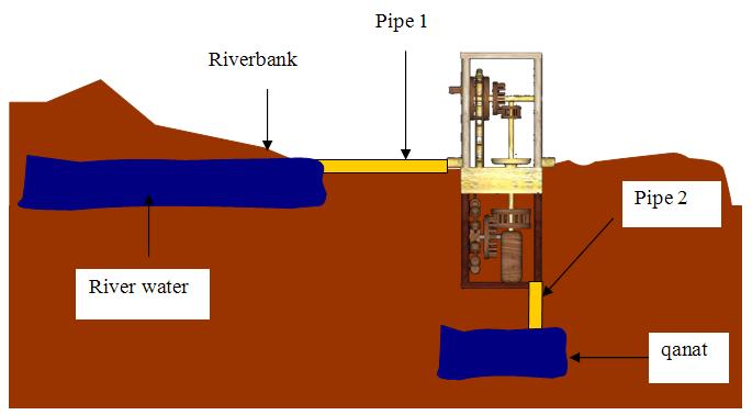 The machine is located beside the riverside where water is fed into the device, through pipe 1, at a controlled rate and later flows out, through pipe 2, from the lower chamber into qanat (man-made underground canals). The qanat has been known and was in use by the 8th century BC, therefore, the time scale for this statement is relevant (see Fig. 26).
6. Rudimentary Components and Materials Used by Al-Jazari
Having a clear understanding of the main mechanism as discussed earlier leads us to find out more about the rudimentary components and materials used by al-Jazari in the construction of the Third Water-Raising Device. Components ranging from bearings to the materials used will be discussed as follows.
6.1. Bearings
Bearings have been used for wheels as early as the fourth millennium BCE in lower Mesopotamia. In addition, metal-to-metal bearings were already in use by the Romans and Greeks, in which Hero of Alexandria mention, in his Mechanics, an axle whose ends were sheathed in copper and ran in copper-covered bearings.It is difficult to assess the standard of craftsmanship attained by al-Jazari in the manufacture and fitting of his axles and bearings, since he tells us so little about them. The bearings are usually shown as rudimentary components on some of the drawings, but then, so are many other parts that we know from the text, to have been made with great care and skill. It is quite likely that they were drawn conventionally, much as a modern designer will show pitch circles for the teeth of a cogwheel.It is justifiable to say that al-Jazari was serious towards his works, therefore he must have took great care to ensure that his wheels were running true. In static balance, this care would have been wasted if there was too much play or friction in the bearings. Thence he categorised different kinds of bearings for different uses as follows:
Plain wooden bearings were said to be in use in the West up to the 14th century. If this is the case, then al-Jazari was considerably in advance of European technology in this respect, since all his bearings are metal-to-metal type. He used different types of bearings for different duties and had a special term for each one. Because of the great care he took in constructing and tuning his machines it seems probable that his bearings were at least adequate, particularly when it is remembered that in most cases, the loads for the devices were light and running speeds were slow [30].
6.2. Axle
Al-Jazari made his axles of wood, copper or iron depending on the duty, and the usual word for them is mihwar, although he occasionally uses non-technical words such as qadib (stick) or saffud (rod). The Banu Musa, Archimedes and al-Khuwarizmi also use the term mihwar [31].
6.3. Lubrication
Lubrication is equally ancient, dating back to Egypt in 1800 BC. An Egyptian wall painting shows 172 men transporting a colossus from a quarry on sledges, while one man pour oil or grease ahead of the base of the statue on which he rides. In addition, Egyptian chariots had plain grease-packed bearings, which were protected from sand by leather covers.The curious point however is that none, not one, of the classical writers, including al-Jazari, makes any mention of lubrication. It could be that they found the process of lubrication to be too common and trivial to be included in their work [32].
6.4. Pipes
The closed pipe system is of interest because al-Jazari incorporates this system to bring in water from rivers to the pool of the invention. Thence it is important to know the characteristics of the closed pipe system. Firstly, the closed pipe system is less expensive as compared to open-channel aqueduct. However, it is much more difficult to construct and requires specialised skills. Moreover, it is subjected to frequent leaks and burst, and if blockage occurs, it may have to be completely dismantled and rebuilt [33].However, al-Jazari and Ridwan used the expression barbakh, which means a short pipe of relatively large diameter. Ridwan tells us that pipes were made by bending sheet copper to a circular cross-section and soldering the edges together. Pipes were joined together by making the end of one wider than the end of the other, and pushing the two together. The wide end was called ‘female’, the narrow ‘male’, exactly as in modern technical parlance. When pipes were to be bent, they were first filled with lead, followed by bending and allowing the lead to melt out [34].Vitruvius suggested a method to seal the joints, crude but practical. That is when the pipeline is complete, and the water is first let into it, some wood ash should be thrown into the tank at the supply end. This will find its way into any cracks or leaks in the system, and help clogs them up. ‘Grouting’ is the technical term [35].
6.5. Fittings
All the Islamic writers used similar methods of connections and fixings. The most common method is soldering, a very ancient technique, probably known 5000 years ago in Ur. Whereby nails, cotters, lugs, male-female joints and push-fit connections were also used extensively, including al-Jazari and Ridwan.While other components such as wire (sharit) was usually made of copper, and chain (silsila) of copper or iron. Rope (habl) was made of hemp or stranded silk. The material used for making string (khayt) is seldom specified, except when it was made of silk. Hinges (namadhaj) were mentioned by al-Khuwarizmi, and were used by all the Islamic writers.An interesting word, used frequently by al-Jazari, is shaziya, translated as ‘activator’, since it seems to be used for any small component, which activates another part of the mechanism. Cams, trip-lugs, push rods, etc. could all be described by this word [36].
6.6. Materials
Most of the materials used by al-Jazari are common to the other Islamic writers, with the some exceptions. The materials are categorised into two groups, namely Metals and Other Materials.a. Metals
The common metals used are iron, lead, tin, gold, silver, copper, brass and bronze. Furthermore the mountains around Diyar Bakr have always been rich in metals. In 516/1122 a copper mine was discovered near Dhu al-Qarnayn. Iron was also plentiful [37]. Therefore these metals are available to al-Jazari, who employed them in the structure of his invention.
b. Other Materials
Al-Jazari had little interest in the use of non-metallic materials, most of which were common substances in everyday use. Wood occurs frequently, in wheels, axles and structural work. The use of lamination to produce a wheel that would not warp is of interest. Other materials used were cloth, leather, linseed oil, paints, paper, and papier mache. Papier mache was used for making Jack Figures when lightness was important, in this case, it would most probably be used for making the cow model.
6.7. Jackwork or Jack Figures
Jackwork refers to human and animal figures, and are found in the works of several Muslim craftsmen and engineers, including al-Jazari. It was thought that Muslims were generally particularly fond of these types of work, as it was some kind of toy.Al-Jazari usually made them from beaten copper, beaten brass, wood, or papier mache. However, the detailed instructions for the manufacture of these figures are often omitted, apart from al-Jazari description of the manufacture of a copper ‘man’ (shakhs), found in Category II Chapter 7.2 of his work, Kitab fi ma‘rifat al-hiyal al-handasiya [38].
7. Weights and Measurements
There was a large number of weights and measures whose values fluctuated widely, depending upon the region, and even upon the choice of the individual craftsman. Ridwan, for instance, used the span of his own hand and the thickness of his own finger for taking measurements. There is little point, therefore, in making a detailed survey of these expressions and their values. Thence only indicative values can be given and these are derived directly from Wiedemann and Hauser.
a. Weights
1 Dirham = 3 gr
1 Mithqāl = 4.5 gr
1 ‘Uqiya (Syrian) = 150 gr
1 Ratl (Damascus) = 1850 gr
1 Mann ≈ 1 kg
b. Measures
1 Dhirā‘ (cubit) = ½ metre
1 Shibr (span) = ½ Dhira = 25 cm.
The span is the distance between the tip of the thumb and the tip of the forefinger, when the hand is outspread. The abbreviation is sp.The span consisted of 12 fingers, placed side by side (asba ‘ madmum). Each finger width was thus equivalent to 2 cm. The abbreviation is F. Sometimes the length of a finger (asba‘ maftūh) was used and this was equal to about 4 cm.Small dimensions are given by the width of a barleycorn (sha‘īra). Laid ‘belly to back’ there were six barleycorns to 1 F. The sha‘īra was therefore equal to about 1/3 cm.The small span (fitr) was the distance between the tips of the thumb and index finger, when outspread. This is taken to be about 16 cm.AI-Jazari also uses the breadth of a fingernail (zufr) say about 1 cm. To indicate very small distances he uses the width of a nail-pairing (qulama) [39].
End Notes
[1] D. R. Hill, A History of Engineering in Classical and Medieval Times, op. cit., p. 128.
[2] See Appendix 11.
[3] D. R. Hill, A History of Engineering in Classical and Medieval Times, op. cit., pp. 144-145.
[4] D. R. Hill, Studies In Medieval Islamic Technology, op. cit., Category VIII, p. 4.
[5] L. Sprague De Camp, The Ancient Engineers, op. cit., pp. 146-147.
[6] See I. 3: Teaching of Islamic Engineering.
[7] Abbott Payson Usher, A History of Mechanical Inventions. Cambridge, Mass.: Harvard University Press, 1954, p. 163.
[8] L. Sprague De Camp, The Ancient Engineers, op. cit., p. 282.
[9] Al-Jazari, The Book of Knowledge of Ingenious Mechanical Devices, op. cit., Part III, p. 275.
[10] A. Y. al-Hassan & D. R. Hill, Islamic Technology, op. cit., p. 70.
[11] See section V.1.5: “John Smeaton Experiment”.
[12] A. Y. al-Hassan & D. R. Hill, Islamic Technology, op. cit., p. 6.
[13] A. P. Usher, A History of Mechanical Inventions, op. cit., pp. 163-164.
[14] See section V.1.5: “John Smeaton Experiment”.
[15] R. J. Forbes, Studies in Ancient Technology. Leiden: E. J. Brill, 1965, vol. 2, p. 42.
[16] Norman Smith, Man And Water: A. History of Hydro-Technology, op. cit., pp. 155-156.
[17] L. Sprague De Camp, The Ancient Engineers, op. cit., pp. 119-120.
[18] Ibid, p. 120.
[19] Ibid, p. 282.
[20] D. A. Agius & R. Hitchcock (editors), The Arab Influence in Medieval Europe, op. cit., p. 38.
[21] Th. F. Glick, Islamic And Christian Spain in The Early Middle Ages, op. cit., p. 237.
[22] See Appendix 8.
[23] Note on fig. 22 and 23 the similarity between these two devices as marked in red.
[24] A. Y. al-Hassan & D. R. Hill, Islamic Technology, op. cit., p. 39.
[25] Ibid, pp. 40-41.
[26] See Chapter III, section 2: The Noria.
[27] D. R. Hill, A History of Engineering in Classical and Medieval Times, op. cit., p. 138.
[28] Th. F. Glick, Islamic And Christian Spain in The Early Middle Ages, op. cit., p. 237. One cubit = 20 inches as stated in L. Sprague De Camp, The Ancient Engineers, op. cit., p. 68.
[29] See IV.2: Description of the Device.
[30] Al-Jazari, The Book of Knowledge of Ingenious Mechanical Devices, op. cit., Part III, pp. 275-276.
[31] Ibidem.
[32] Ibidem.
[33] J. G. Landels, Engineering in the Ancient World, op. cit., p. 42.
[34] Al-Jazari, The Book of Knowledge of Ingenious Mechanical Devices, op. cit., Part III, p. 276.
[35] J. G. Landels, Engineering in the Ancient World, op. cit., p. 44.
[36] Al-Jazari, The Book of Knowledge of Ingenious Mechanical Devices, op. cit., Part III, p. 277.
[37] Ibidem.
[38] Ibidem.
[39] Ibid, p. 278.
VI. Mathematical Analysis
1. Analysis of the Total Head of Water Jet
The purpose of this analysis is to find the total head of water. A set of detailed calculation and explanation can be found in Appendix 11. The formulas in Appendix 11 used for finding this force is simplified and derived as shown below. These formulas are also programmed into Microsoft Excel programme to calculate the total head for variable conditions.
The Total Head of Water Jet:
HT = HW + HAB – [(tanθ)(rscoop)]
Where
HW = head of water surface to bottom of pool
HAB = half the height of the lower chamber
Θ = angle of strike
rscoop = radius of scoop-wheel.
The above variables are to be inputed into the Microsoft Excel programme for an estimation of the total head of water jet.
2. Analysis of the System of the Third Water Raising Device
The purpose of this analysis is to find the resulting force capable of raising water. A set of detailed calculation and explanation can be found in Appendix 12. The formulas in Appendix 12 used for finding this force is simplified and derived as shown below. These formulas are also programmed into the Microsoft Excel programme to calculate the force for variable conditions.
The force of the water jet:
Fj = 2 g HT ρ π(rj)2
The force transfer from the jet to the bucket:
FT = 2 g HT ρ π(rj)2 (1 – V*)(1 – cos θ)
The force applied on gear A:
FA = {(1 – μ) [(1 – μ)FT rscoop]} / rA
The Force applied on Gear B
FB = (1 – μ)FA
The Force applied on Gear C
FC = [(1 – μ) (FB rB)] / rC
The Force applied on Gear B
FD = (1 – μ) FC
The Force applied on Sindi Wheel
Fsindi = [(1 – μ) (FDrD)] / rsindi
The Weight of Water Raised:
mwater = Fsindi / g
Where
HT = total head of water jet
ρ = density of water
rj = radius of jet outlet
V* = scaled bucket speed
= deflection angle for the bucket
= coefficient of friction
rscoop = radius of scoop-wheel
rA = radius of Gear A
rB = radius of Gear B
rC = radius of Gear C
rD = radius of Gear D
rsindi = radius of sindi wheel
The above variables are to be inputted into the Microsoft Excel programme for an estimation of the force capable of raising water and the weight of water raised.
3. Assumptions and Considerations
For the mathematical analysis of the system, several assumption and considerations were taken for the most optimal conditions. The more significant ones are the deflection angle for the bucket, θ, and the maximum weight of water being raised.
3.1. Deflection Angle for the Bucket
The typical deflection angle for the bucket is taken at the most optimal condition when it is at the horizontal position, where θ 1 is equal to θ 2 (see Fig. 27). However the deflection angle will vary as the bucket rotates, at this point, θ 1 is not equal to θ 2 (see Fig. 28). Although a more accurate force might be obtained by calculating this difference, it is noted that the difference in θ will be minute and that using the typical value of 165° is more appropriate.

Figure 27: The bucket in horizontal position during rotation.

Figure 28: The bucket deflected at angle during rotation.
3.2. Maximum Weight of Water Being Raised
Once the force capable of raising water is found, the maximum weight of water being raised can be found by Fsindi = mwaterg, on the assumption that the weight of the copper jars are in equilibrium or symmetry is maintained during the cycle, m1r1 = m2r2 (see Fig. 29). This is attributed to the fact that the weight of the copper jars would counter-balance, thence would be equilibrium.
However, it would not be true when the copper jars are in motion as there would be a difference in moment, m1r1 ≠ m2r2 (see Fig. 30). An opposing torque, TO, will therefore be applied against the torque produced by the force applied on the Sindi Wheel, Tsindi. Therefore the torque applied to raised water, Tw = Tsindi – To.
Although a more accurate value of the weight of water might be obtained by calculating this difference, it is noted that the difference will be minute and that using the formula Fsindi = mwaterg, is more appropriate.

Figure 29: The copper jars in symmetry.

Figure 30: The copper jars during rotation.
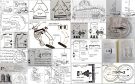
VII. 3D Graphics and Animations
Visual aids such as 3D graphics and animations play a very important role in this report, as they show a clearer picture of the device to the reader. 3D graphics and animations are constructed, using 3D Studio Max R3.1, based on the findings on the research and mathematical analysis done (see Fig. 31). These graphics and animations are used in the report as visual aids for better understanding of the device.
The 3D graphics in this chapter shows the device in different angles of views, close-up views and ‘wireframe’ views (see Figures 32 to 42). The different angles of views include the front perspective view, rear perspective view, front view and left view. The close-up view zoom in onto the chambers of the device in perspective view while the ‘wireframe’ view shows the ‘skeleton’ view of the device.
The 3D animations consist of two movie files; namely a 360° rotational view and one that shows the movement of individual components during its operation. These animations enable the reader to view the device in different angles and also the view of the device in operational mode.

Figure 31: 3D Construction of the Third Water Raising Device.

Figure 32: Front Perspective View.

Figure 33: The Rear Perspective View.
1. Identification of Parts

Figure 34: The identification of different parts of the Third Water Raising Device.

Figure 35: The Close-Up View of the Upper Chamber.

Figure 36: The Close-Up View of the Lower Chamber.

Figure 37: The Close-Up View of the Upper Chamber.

Figure 38: The Close-Up View of the Lower Chamber.

Figure 39: The Front View.

Figure 40: The Left View.

Figure 41: The ‘Wireframe’ Front View.

Figure 42: The The ‘Wireframe’ Rear View.
VIII. Conclusion
The flourishing of Islamic Studies was attributed to the success of the developing technology, which utilised natural forces within the environment to do work. Islamic technology was branched into Fine Technology and Utilitarian Technology. The Third Water Raising Device incorporated these two branches together, an ingenious invention by al-Jazari.
Al-Jazari was an inventor who described in scrupulous detail how each device was constructed. He was also a ‘ra’īs al-a‘māl’, which in modern terms is a “Chief Mechanical Engineer’. He reached this superior position on the basis of his extensive experience; having profound understanding of pure science on the one hand, and his mastery of practical skills on the other. In his treatise A Compendium on the Theory and Practice of the Mechanical Arts, emphasises the importance of experimentation and precise observation and will not entertain much faith in findings unsubstantiated by experiment.
The Third Water Raising Device is an example of his detailed description with constant reference to the drawing depicting the device. However, on occasions, he tends to be inconsistent in his dimensions, inability to give a coherent record of mathematical or geometrical process and having some vagueness about the positioning of the components. An interesting feature in this machine is the wooden animal that is fixed to the rotating circular disc giving the impression that this machine is driven by an ox. This is, perhaps, a way of avoiding being accused of designing a machine driven by some witchcraft or a jinni. Another explanation is that this machine is designed to work on both modes; automatic or animal driven, although there is no description of the latter mode.
Based on al-Jazari’s description, the construction of 3D graphics of the device began. However, problems were faced as he fails to state the kind of gears and rudimentary components that he might have used. Furthermore, he fails to mention several dimensions, such as the overall size of the device. In addition, the unit scales that he had used were ancient Arabic units. Thence research work had to be done to answer these queries.
A mathematical analysis of the system is also essential to analyse the overall capability of the device. According to the mathematical analysis, the system is capable to produce large force to raise relatively large amount of water. The formulas used are simplified and programmed into Microsoft Excel programmes for variable condition analysis.
Based on these findings, 3D graphics and animations were constructed and dimensions that were omitted initially were estimated instead. The 3D graphics and animations brought to life the device in working condition, where the movement of each component was estimated from the mathematical analysis. Furthermore, the 3D graphics and animations were used as visual aids in this report for better understanding of the device.
The Third Water Raising Device is relatively small in size as compared to al-Jazari’s other water raising devices. Expensive materials such as copper, silk and marble were used for the construction to enhance its appearance. However, the device is designed to raise relatively small amount of water as al-Jazari states that each copper jar would carry only 9 grams of water.
One may argue that the device might be unrealistic, with the use of heavy and expensive components such as copper jars that might affect the overall efficiency of the system. Furthermore, it is unrealistic to employ the use of a large amount of water to drive a device that raise a relatively small amount of water. However it is important to state that the device described in al-Jazari’s book was a small demonstration model invented for the courtly circle.
In conclusion, although the Third Water Raising Device has several doubtful faults in modern engineering terms, it might be considered as a technology breakthrough during the 13th century. Considering that this device incorporates the use of waterpower to drive a series of gears and finally the Sindi Wheel to raise water, an automated process that requires the presence of neither man nor animal. A success attributed to the ingenious inventor and engineer, al-Jazari.
IX. References
1. General
Agius, Dionisius A. & Hitchcock, Richard (editors), The Arab Influence in Medieval Europe: Folia Scholastica Mediterranea. Ithaca Press, 1994.
Al-Hassan, Ahmad Y., Hill, Donald R., Islamic Technology: An Illustrated History. Cambridge. Paris/Cambridge: UNESCO/ Cambridge University Press, 1986.
Al-Jazari, Ibn Al-Razzaz, The Book of Knowledge of Ingenious Mechanical Devices. Translated and Annotated by Donald R. Hill. Dordrecht: D. Reidel, 1974.
Al-Jazari, Al-Jāmi‘ bayn ‘l-‘ilm wa ‘l-‘amal al-nāfi‘ fī sinā‘at al-hiyal [A Compendium On The Theory And Practice Of The Mechanical Arts]. Arabic text edited by A. Y. al-Hassan et al. Aleppo: Institute for the History of Arabic Science, 1979.
Cursetji Pavry, Jal Dastur (editor), Oriental Studies in Honour of Cursetji Erachji Pavry. London: Oxford University Press, 1933.
Forbes, R. J., Studies in Ancient Technology. Volume 2 . Leiden: E. J. Brill, 1965.
Glick, Thomas F., Islamic And Christian Spain in The Early Middle Ages. Princeton: Princeton University Press, 1979.
Hayes, John R. (editor), The Genius of Arab Civilization Source of Renaissance. Oxford: Phaidon Press, 1976 (reeditions London: Escovitz, 1983; Cambridge, Mass.: The MIT Press, 1978, 1984).
Hill, Donald R., “A Treatise on Machines by Ibn Mu‘ād Abū ‘Abdallāh al-Jayyānī.” Journal for the History of Aarabic Science vol. 1 (1978): pp. 33-44. [See also on the same text A. I. Sabra, A.I., “A note on Codex Medicea-Laurenziana Or. 152”, Journal for the History of Arabic Science vol. 1 (1977): pp. 276-283].
Hill, D. R., A History of Engineering in Classical and Medieval Times. London/New York: Routledge, 1984.
Hill, D. R., Islamic Science and Engineering. Edinburgh: Edinburgh University Press, 1993.
Hill, D. R., Studies In Medieval Islamic Technology. From Philo to al-Jazarī-From Alexandria to Diyār Bakr. Edited by David A. King. (Variorum Collected Studies Series). Aldershot, Eng. /Brookfield, Vt.: Ashgate, 1998.
Landels, J. G., Engineering in the Ancient World. London: Chatto and Windus, 1980 (1st edition 1978).
Nasr, Seyyed Hossein, Islamic Science: An Illustrated Study. Photographs By Roland Michaud. London: The World of Islam Festival Trust, 1976.
Smith, Norman, Man And Water: A. History of Hydro-Technology. London: Peter Davies, 1976 (1st edition New York: Scribner, 1975).
Sprague De Camp, L., The Ancient Engineers. Garden City, N.Y.: Doubleday, 1963.
Usher, Abbott Payson, A History of Mechanical Inventions. Cambridge, Mass.: Harvard University Press, 1954. (Revised edition: Dover Publications, 1988).
2. References for Mathematical Analysis
White, Frank M., Fluid Mechanics. Third Edition. Maidenhead, Berkshire: McGraw-Hill Higher Education, 1994. (5th revised edition, 2003).
James M. Gere, Stephen P. Timoshenko, Mechanics of Materials. 4th Edition. Boston: PWS Pub. Co., 1984.
Joseph E. Shigley, Charles R. Mischke, Mechanical Engineering Design. Fifth Edition. McGraw-Hill, 1989.
*1Salim T. S. Al-Hassani – Foundation for Science, Technology and Civilisation, Chairman of the Board, and Emeritus Professor at the University of Manchester.
2Colin Ong Pang Kiat – Final Year Student (2001), Mechanical Engineering, MACE, University of Manchester, UK.
Discover the golden
age of Muslim civilisation.
© Copyright FSTC Ltd 2002-2020. All Rights Reserved.