In his book The Brightest Stars for the Construction of Mechanical Clocks (Al-Kawakib al-durriyya fi wadh' al-bankamat al-dawriyya), Taqi al-Din Ibn Ma'ruf analyses the four main types of time keeping devices known in the 16th century: watches, domestic clocks, astronomical clocks and tower clocks. Such machines represent the earliest mechanical computers. In the following, we present for the first time a virtual reconstruction of the astronomical clock type through geometrical drawing and 3D animation.

By Salim T S Al-Hassani*
Table of contents
3.1 The First Chapter
3.2 The Second Chapter
3.2.1 Striking Trains
3.2.2 Alarm
3.3 The Third Chapter
3.4. The Fourth Chapter
3.5. The Fifth Chapter
4. Preliminary Calculations for the First Chapter
4.1. Calculations for the Correct Gear-Teeth Ratios
4.2. Calculations of the Forces that the Drum Would Need to Overcome
***
In his book The Brightest Stars for the Construction of Mechanical Clocks (Al-Kawākib al-durriyya fī wadh’ al-bankāmat al-dawriyya), Taqī al-Dīn Ibn Ma‘rūf (born in Damascus in (1526 – died in Istanbul in 1585) analyses the four main types of time keeping devices known in the 16th century: watches, domestic clocks, astronomical clocks and tower clocks. Such machines represent the earliest mechanical computers. In the following article, we present for the first time a virtual reconstruction of the astronomical clock type through geometrical drawing and 3D animation.
 |
|
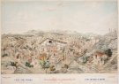
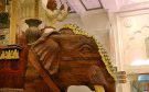
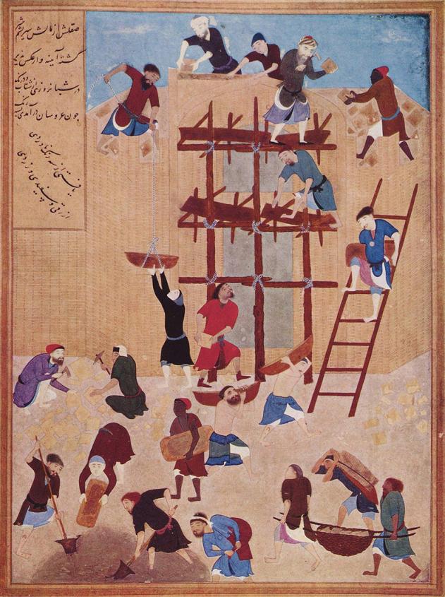
Figure 1: Taqī al-Dīn’s observational clock is shown in the right hand side middle of this famous picture of Istanbul observatiry. Source: Istanbul University Library, MS F1404, folio 57a. |
The treatise Al-Kawākib al-durriyya fī wadh’ al-bankāmat al-dawriyya (The Brightest Stars for the Construction of Mechanical Clocks) is extant in several manuscript copies. They are preserved respectively in Cairo (Dār al-kutub, MS Miqat 557/1, 35 folios, MS Falak 3845, MS Sinā‘a 166/1, 49 folios), Oxford (Bodleian library, MS 968, 60 folios), and Istanbul (University Library, MS 966 and 1552) [1]. There is also a manuscript copy of the same book (Bibliothéque nationale, MS arabe 2478, 85 pp.) entitled Risāla fī ‘ilm al-binkāmāt (Treatise in the science of clocks) [2]. Two more copies of the book exist respectively in Chester Beatty Library in Dublin (Arabic MS 5232, 44 folios), and in Kandilli Rasathanesi Library in Istanbul (MS 96, 46 folios). The later manuscript include 52 images and 7 miniatures [3]. The book was edited and translated by Sevim Tekeli [4].
The book was dedicated to the minister Alī Pāshā, a dignitary of the Ottoman state who was nominated as governor of Egypt in 956 H/1549, and who was the patron of Taqī al-Dīn since then. In the colophon of the text, the author asserts that he wrote his book in 966 H/1559 in Nablus, Palestine, where he was a judge there. In addition, he mentions in the foreword that he benefited from using Alī Pāshā’s private library and his collection of European mechanical clocks [5].
Al-Kawākib al-durriyya fī wadh‘ ‘l-bankāmāt al-dawriyya is the first known treatise written in the Islamic world about mechanical automatic clocks. Having been in contact with the European clocks, which began to arrive in Istanbul from the beginning of the 16th century [6], Taqī al-Dīn as an accomplished engineer may have wanted to make a progress in the Islamic tradition of clock designing and manufacturing along the same lines of automatic mechanisms.
In this article, we reconstruct for the first time the astronomical clock designed by Taqī al-Dīn for astronomical observation. We rely in this reconstruction on the original descriptions provided by the author in his treatise, which we approach through mathematical and physical analysis. The clock is described in the first article of Al-Kawākib al-durriyya. This article is composed of five chapters. The fact that Taqī al-Dīn chose to begin his treatise by this fascinating clock is a testimony to its importance in his eyes.
Before the 16th century, clocks were considered too inaccurate for measuring celestial movements. Where Ptolemy failed to succeed in, Taqī al-Dīn planned to build an astronomical clock that would measure time with great regularity in fulfillment of the wish of the Sultan at the time.
Using mathematics, he designed three dials which showed the hours, degrees and minutes. In his clock, he incorporated the use of several escapements, an alarm, the striking trains that sounded at every hour, the visual relationship between the sun and the moon, the different phases of the moon, the devices that indicated the time for prayers and the dials that showed the first day of the Gregorian months.
Taqī al-Dīn’s work on mechanical clocks is of important significance in light of transmission of knowledge between cultures and advancement of technology within the Middle East in the middle of the 16th century. Many of the devices mentioned in his clock are present in today’s clocks from all around the world.
 |
|
Figure 2: The Escapement Mechanism generating incremental movement of the crown wheel. |
For example, the escapement is the heart and soul of a clock. It governs the regularity of the clock, enabling it to move in an incremental manner. It is interesting to see that many modern day clocks still rely on the same device. In the latter part of the book, Taqī al-Dīn describes a clock powered by springs, and indeed, springs were used in the development of watches.
Another example is the alarm arrangement. Taqī al-Dīn’s clock is capable of sounding at a specified time. This was achieved by means of placing a peg on the dial wheel to when one wants the alarm heard. Not only was he set out to construct a device that could reliably and regularly measure time, Taqī al-Dīn auspiciously produced an automated ringing device, an ingenuity we have taken for granted in modern society.
 |
|
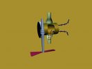
Figure 3: Novel gravity system introduced as a source to power the clock. |
|
Click here to view the 3D animation. |
An advancement that does not immediately appear evident is the power source of the clock. Before the 16th century, clocks were powered by running water. The earliest form was the clepsydra, a type of vessel with water emptying from it at a constant rate with the level of water indicating the number of hours on the side. Taqī al-Dīn has progressed onto using falling weights which can be easily recoiled to restart the clock. This is evidently still in use in today’s grandfather clocks.
Taqī al-Dīn acknowledged the craftsmanship required to make such time measuring instruments. He would state the materials used and design gears in such a way that the main body would be hollow to reduce weight. He gave instructions in making drums and insisted that bobbins were used so that drums and gears were free to rotate.
In the 16th century, clocks were beginning to be regarded as astronomical instruments due to improved timekeeping. Perhaps this was due to Taqī al-Dīn who was a pioneer in this field, as Langraf William IV of Hesse and Tycho Brahe of around 1580 made considerable progress in developing astronomical clocks.
Taqī al-Dīn must have been aware of many clock-making techniques through studying the work of other people. We are not sure if he was the first to invent the spring powered clock. The evidence so far shows that Peter Heinlein might have been the first person to achieve a spring powered watch in 1524, he managed to incorporate the spring into his clock in 1556, while the first spring powered watch did not appear in England until 1580.
It is reasonable to say that from observing other clocks, he was able to offer several alternatives for constructing any particular part of the clock. Six methods were given for constructing the striking trains in the first section of Chapter two. The simplest configuration would be given first, with the rest being alternatives or more elaborate and accurate versions of the first one. The sixth method is his invention accompanied with a lot more detail. He described methods of constructing certain parts by educated trial and error as well as safety issues to be concerned with to maintain accuracy. Research engineers of today follow similar course of practice in their work when they want to determine the best solution. Similarly, his chapter three describes seven ways in displaying the phases of the moon, days of the week and degrees of the day.
During his observations, he appreciated that there is a dual system of telling time. Throughout the book, he would state different construction methods for a 12 hour and a 24 hour clock.
Taqī al-Dīn showed incredible foresight into the human needs and practicality of mechanical clocks. So much so, his impact has been significant to the development of clocks and watches. His understanding and careful choice of methods employed in constructing such clocks can only was excellently contrived and planned for someone of this period.
The article is divided into chapters in the same order as Taqī al-Dīn had structured his book. Each chapter describes one technical aspect of the construction of the clock.
The first article is divided into five chapters concerning weight driven clocks. These were powered by a falling weight attached to a cord.
3.1 The First Chapter
Shown in this chapter are the rotational systems of the dial wheel. Taqī al-Dīn mentions that iron, brass, steel and wood materials are available for the construction of the gears. The choice of material depends on the size of the gear (its diameters and the number of teeth).
 |
|
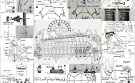
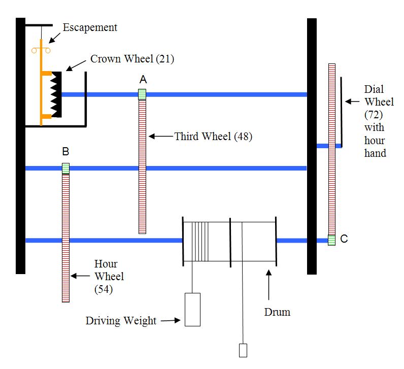
Figure 4: Schematic side view of the main mechanisms in the clock. |
Figure 4 shows a schematic diagram of the set up. The system is powered by the driving weight of the drum. The escapement is shown in orange. By transmission of power through the different pinions (green) and gears (red), the dial wheel is rotated with the hour hand attached to it indicating the number of hours passed. The thick black lines are the supporting structure for the clock. The number of teeth for each gear is shown in brackets and there are six teeth on each pinion A, B and C.
The driver consists of a drum attached to a rope which is connected to a weight and the rope is then wound onto the drum. The driver turns by the fall of the weight. The gear nearest the driver is the slowest of all, but is also the strongest in pulling. The further the gears are from the driver, the more rotations they perform with weaker power.
The drum itself is made by rolling a sheet of brass and joining it where they meet. The caps at either end are concaved with bobbins attached at the rotational centre where an axle can be inserted. The hollow drum is a means to reduce mass affecting the fall of driving weight.
 |
|
Figure 5: Details of the escapement and top view of the pallets. |
The important mechanism involved in prolonging the fall of the driving weight is known as the escapement, which consists of a verge and a foliot as shown in figure 4. The verge is described as pivoting on one end, and attached to a piece of thread on the other so as to experience as little friction as possible. The foliot is like a pair of arms joined at the top of the verge. Along it, weights or “bracelets” can be slid along the foliot to adjust the speed at which it rotates. Along the verge are two pallets with an obtuse angle between them. The distance at which they are separated along the verge is dependent on the diameter of the crown wheel. The pallets are in contact with the teeth of the crown wheel and it is these that give the clock the characteristic incremental movement.
Taqī al-Dīn would offer alternatives in gear configuration and the way power is transferred from one gear to another. For example, there was a series of two gears where the power can be transferred by pinions or alternatively by the use of a belt in place of gear teeth, here he does mention that the former method is the best possible solution.
The gears themselves have areas cut out of them to reduce weight. They are likely to be made out of brass with the axles made of steel given it has stronger properties than brass.
3.2 The Second Chapter
The details of the mechanisms of the striking trains and the alarm are shown here. The former indicates the number of hours passed by sounding a bell via a strike of the hammer. So for one hour passed, one strike of the bell is made, two hours passed two strikes are made etc. The latter rings the bell at a specified time.
3.2.1 Striking Trains
 |
|
Figure 6: Schematic diagram of the striking train system. |
The following description is for a 12-hour dial clock. This striking train system is independent of chapter one, but the author believes it is positioned to the left side of the system in figure 4.
There is a driver similar to that in chapter one. This is the power source for the striking trains. On the same axle is a pin wheel which has 6 pins set perpendicular to the surface. Along its perimeter are 48 teeth found on a typical gear, shown in figure 6.
Engaged with the pin wheel is an eight teeth pinion (C). Along the same axle, there is a hoop wheel (42) with what is described as a count wheel is attached to it. The count wheel is a circular plate of half the diameter of the hoop wheel, and has slots cut into it as shown in figure 7. The slots correspond to the degrees the count wheel rotate for each hour in order for the clock to ring once for the first hour, twice for the second hour etc.
 |
|
Figure 7: Count wheel. |
A pinion of six teeth (B) is engaged with the hoop wheel. Along that same axle, an upper wheel (36) is attached. A six teeth pinion (A) is engaged with the upper wheel. Along the end of that axle, a fan that is big enough to prevent the motion of the underneath gears from proceeding too fast is attached.
The housing of the clock is mentioned, although very unclear, Taqī al-Dīn suggests that the iron framework can consist of either four cylinders, a base and a roof, held together by nails and screws or welded together. The base and roof can be shaped as either square, hexagonal or circular. Along the roof perimeter, numbers one to eight are labeled equally along it.
 |
|
Figure 8: Examples of clock housing framework. |
The pins of the pin wheel are engaged with a tongue, as shaped in figure 8. The tongue is connected to the spring which is in tension and with a hammer. As the pin wheel rotated, a pin pushes up the tongue, which sends the hammer swinging backwards. When the pin is released from the tongue, the spring recoils to its initial position, swinging the hammer in the opposite direction thus striking the bell to indicate the hours.
The number of corresponding strikes of bell to the number of hours is achieved by levers or as ‘detent’ termed by Taqī al-Dīn. They transmit the motion of the hour wheel to releasing the count wheel lever which enables the striking trains to strike the bell.
The hour wheel lever is pivoted on the side pillar of the housing frame and in-line with the pin on the hour wheel. The count wheel lever is pivoted on the central pillar, and placed slightly higher than the count wheel, such that it is able to fall into the count wheel’s slots. The two levers are connected by a rigid link, so that when one moves, the other moves with it.
 |
|
Figure 9: Side view of striking train. |
The hour wheel completes one full rotation in one hour. At the turn of each hour the pin of the hour wheel will raise the hour wheel lever. The hour wheel lever raises the count wheel lever and the count wheel is freed. The count wheel and its associated gears will now rotate, thus the bell will be rung. Due to the arrangement of slots on the count wheel, the count wheel lever will fall due to gravity in the next adjacent slot and will stop again and both detents would be back in there resting positions until the next hour.
The accuracy of the intervals between slots was calibrated manually in a trial and error method. Firstly, the pin wheel has 6 pins (although more is a possibility), when the count wheel is free from its lever, the pin wheel will rotate and ring the bell with the hammer. The number of times the bell is struck is determined by the positions of the slots in the count wheel. By initially cutting a slot as a reference point, one can then rotate it (with the lever disengaged) and turn the mechanism to strike the bell once. By using the lever, a new slot can be marked and cut out. The count wheel can then be turned to sound the bell twice and using the detent again, a new slot can be cut. The procedure is repeated until all hours are accounted for.
The levers themselves have elaborate ends designed for hooking or engaging the count wheel more effective. Taqī al-Dīn has given many examples of lever ends. Here, the author has chosen the butterfly lever for the count wheel engagement.
 |
 |
|
Figure 10: Examples of levers with ends designed for hooking or engaging the count wheel. |
Figure 11: Three dimensional view of the Striking Train. |
3.2.2 Alarm
 |
|
Figure 12: Schematic diagram of the alarm system. |
It is unclear from the original text as to where the alarm is placed. Although Taqī al-Dīn does mention that it is small enough to fit above the crown wheel (in chapter one), between the axle of the dial wheel and the axle “parallel to the crown wheel”, the latter description is quite unclear.
A flat annular plate is attached to a few dowels which are attached to the back of the dial wheel, so the annular plate is slightly elevated from the surface of the dial wheel. Along the perimeter of the annular plate are holes which allow a peg to be pushed in. The peg specifies when the alarm should sound. So the hour or degree of an hour the peg is placed in will be the time in which the bell rings.
 |
|
Figure 13: Front and side view of the dial wheel. |
The mechanism labeled the “bird end” by Taqī al-Dīn, is connected to the “bird” and the “dragon”, where there is a pivot at the bird. The bird-dragon mechanism prevents the verge, hence the foliot and crown wheel, from rotating. When the peg from the dial wheel comes in contact with the bird end, the peg pushes the whole mechanism so that it disengages itself from the verge. The weight of the alarum wheel is allowed to fall, turning the crown wheel, but its descent prolonged by the escapement, and at the same time, ringing the bell.
The dragon is latched onto the verge which prevents it from moving. The part of the verge that is in contact with the dragon must be machined accommodate it.
Again, Taqī al-Dīn offers several positions for the bell. One position involves the foliot being inside the bell, so the foliot acts as the hammers to sound it. The second position involves the hammer being outside the bell. The third position is shown in figure 15 and is the one chosen out of simplicity since using the foliot as a hammer can hinder the movement of the crown wheel and alarum wheel.
 |
 |
|
Figure 14: Bird-Dragon mechanism. |
Figure 15: Dragon and verge connection. |
3.3 The Third Chapter
Here the description of the motion and faces of the moon, the days of the week, position of moon in the lunar cycle and the hours of the day are shown.
Seven methods were illustrated with most of them showing the same display configuration with differences only in the construction of the gears and where they are situated within the clock. The following description will concentrate on the fifth way as designed by Taqī al-Dīn.
 |
|
Figure 16: Configuration of display wheel and view from the front facade. |
The display wheel is called the black moon and is similar to the crown wheel, in that it has sawtooth teeth along its perimeter. There are 60 teeth for the 12 hour clock and Taqī al-Dīn describes the method set out to produce 60 along its perimeter with accuracy.
On the display side, one circle of half the size of the black moon is drawn along its diameter. This circle is painted black with the surroundings painted white with silver borax. A circular disc of the same size and colour as the painted circle on the black moon is made. However, the author believes that this particular disc should be white so as to emphasize the phase of the moon. A small loop is made on its perimeter where it is attached to the axle of the black moon.
A seven teeth gear named the wheel of week is divided into seven equal segments with the days of the week written in each segment. It is engaged with the black moon and turns daily to reveal the day of the week.
3.4. The Fourth Chapter
The mechanisms involved in setting the correct degrees of movement appropriate for the external displays described in chapter three.
It is unclear what all the labels on the great wheel represent. The author has determined that the inner circle represents constellations such as Aries and Scorpio. Taqī al-Dīn has mentioned the phases of the moon, however, he doesn’t mention where about on the wheel this is shown. The author can only imagine that the eight segments on the outer circle represent the eight phases of the moon. It is still unclear what the fifteen segments imply.
Although the cycle of the moon is continuous, there are eight distinct phases as Taqī al-Dīn so rightly observed and these distinctions are still used today. The phases designate the degree to which the moon is illuminated and the geometric appearance of the illuminated part. The sequence of the phases is:
1. New moon – the moon is not visible
2. Waxing crescent – the moon is partly illuminated but not beyond half way.
3. First quarter – half of the moon is visible by direct sunlight.
4. Waxing gibbous – more than half the moon is visible.
5. Full moon – the whole face of the moon is illuminated by direct sunlight.
6. Waning gibbous – similar to the waxing gibbous but with decreasing illumination.
7. Last quarter – only half the moon is illuminated.
8. Waning crescent – the moon is partly illuminated by not beyond half way.
 |
|
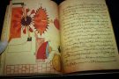
Figure 17: The great wheel. |
The great wheel is situated behind the moon gears as described in chapter three. The façade of the clock would have sections cut out to reveal the zodiac, moon phase and the 15 segments. The moon phase displays were referred to mechanical clocks of Istanbul in 1556 to make the clock more beautiful.
In this chapter, figurines were described to appear and disappear whilst drumming, trumpeting, ringing a bell, dancing or whistling. He does not describe their methods of construction and how their movements were driven.
3.5. The Fifth Chapter
Improvement in clock accuracy and constructions are discussed here. Ease of maintenance of the clock and ways of regulating it are also considered in five given examples. However Taqī al-Dīn fails to mention the situations of when such improvements should be incorporated.
The descriptions given are somewhat vague as they refer to points on the framework of the clock, which were not properly stated in the previous chapters. He touches upon topics such as the positioning of the gears and extra components added in order to release the crown wheel to make necessary adjustments when it is out of time.
 |
|
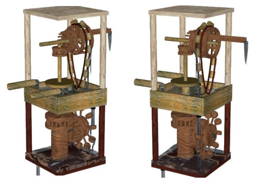
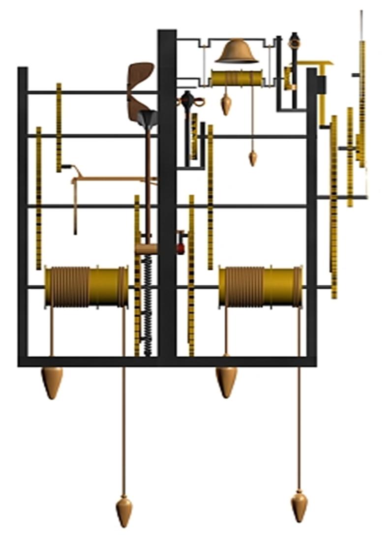
Figure 18: Overal mechanism of the clock. |
|
Click here to view the 3D animation. |
Finally, in the second article of the book, a part of the clock is described. This concerns a spring powered clock. Currently this is still under research and should be referred to the author if information is required.
4. Preliminary Calculations for the First Chapter
The mathematical basis of the clock designed by Taqī al-Dīn in the first chapter of his treatise Al-Kawākib al-durriyya fī wadh’ al-bankāmat al-dawriyya are presented in this section.
The escapement (coloured orange) is the mechanism used to prolong the fall of the larger weight of the drum. Through the transmission of power through the different pinions (green) and gears (red), the dial wheel is rotated, whereas the hour hand attached to it indicates the number of hours past. The thick black lines are the supporting structure for the clock. The number of teeth for each gear is shown in brackets and there are six teeth on each pinion A, B and C.
 |
|
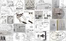
Figure 19: Schematic diagram of the internal workings of the clock. |
4.1. Calculations for the Correct Gear-Teeth Ratios
Taqī al-Dīn has mentioned that for one hour, 1512 crown wheel teeth will have to pass in front of each pallet of the escapement. The pallets are the orange parts in contact with the crown wheel. This number is true if the gears and pinions have the labelled number of teeth shown in the following:
Assuming that the dial wheel (72) represents a 12 hour clock, then
72 teeth / 12 hrs = 6 teeth/hr
Since C has 6 teeth, this implies that one revolution of C will represent one hour. C and the hour wheel (54) are both on the same axle, so the hour wheel will complete one revolution simultaneously with C. The hour wheel is connected to B meaning that B will complete 9 revolutions (54/6).
The third wheel (48) will also complete 9 revolutions since it is on the same axle as B. So 432 teeth will pass in front of A (9×48).
The 72 revolutions made by A (432/6) would mean that the crown wheel (21) also performs 72 revolutions. So the total number of teeth that passes in front of each pallet is 1512 (21×72).
4.2. Calculations of the Forces that the Drum Would Need to Overcome
 |
 |
|
Figure 20 |
Figure 21 |
Dimensions:
They need to be established before any calculations can be done.
Assume : The tooth thickness is 1cm [7]
The tooth height is 1.5mm
For all gears except the crown wheel.
Assume: The shape of the crown wheel teeth is the following:
Dial wheel has 72 teeth
The circumference of the dial wheel would be: 72 x 0.01 = 0.72m
Thus the diameter of the dial wheel is:
Ddial = 0.72 / π = 0.23m
The same calculations are made for the other gears:
| Gear | Number of teeth | Circumference (m) | Diameter (m) |
| Dial | 72 | 0.72 | 0.23 |
| Hour | 54 | 0.54 | 0.17 |
| Third | 48 | 0.48 | 0.15 |
| Crown | 21 | 0.21 | 0.07 |
| Pinion | 6 | 0.06 | 0.02 |
Materials and mass:
Assume: density of water is 1000kgm-3
| Material | Specific Gravity | Density (kgm-3) |
| Iron | 7.85 | 7850 |
| Brass | 8.4 | 8400 |
| Steel | 7.8 | 7800 |
| Wood | 0.55 | 550 |
Assume: 50% of the material is removed from each gear (except the pinion) to reduce weight. Brass is chosen for the material of the gears.
For the mass of the dial wheel is:
Volume = πd2 / 4 L = π(0.23)2 / 4 x 0.01 = 4.15 x 10⁻⁴m3
So the mass of the dial wheel will be half of the total mass of the gear:
Mass = 1/2 x 8400 x 4.15 x 10-4 = 1.74kg
The same method is applied to the other gears:
| Gear | Diameter (m) | Volume (m3) | Mass (kg) |
| Dial | 0.23 | 4.15 x 10⁻⁴ | 1.74 |
| Hour | 0.17 | 2.27 x 10⁻⁴ | 0.95 |
| Third | 0.15 | 1.77 x 10⁻⁴ | 0.74 |
| Crown | 0.07 | 3.85 x 10⁻⁵ | 0.16 |
| Pinion | 0.02 | 3.14 x 10⁻⁶ | 0.026 [8] |
Assume:
No friction between axles and gears as they are fixed to each other
Driving weight = 0.5kg
Friction of coefficient μ = 0.1 for gear engagements.
Force exerted by driving weight:
Fdrive = 0.5×9.81 = 4.91N
The hour wheel and driving drum are on the same axle:
Fdrive = Fhour
Thus torque of the hour wheel is:
Thour = Fhourx rhour = 4.19x 0.17 / 2 = 0.417Nm
Friction between hour wheel and pinion B:
Fμ = μFhour = 0.1×4.91 = 0.491N
Tμ = Fμx rhour = 0.491x 0.17 / 2 = 0.0417Nm
Torque at B:
TB = Thour – Tμ = 0.417 – 0.0417 = 0.375Nm
Force at B:
FB = TB / rB = 0.375 / 0.01 = 37.5N
The third wheel and pinion B are on the same axle:
Fthird = FB
Torque of the third wheel:
Tthird = Fthird x rthird = 37.5 x 0.15 / 2 = 2.81Nm
Friction between the third wheel and pinion A:
Fμ = μFthird = 0.1×37.5 = 3.75N
Tμ = Fμ x r third = 3.75 x 0.15 / 2 = 0.281Nm
Force at A:
TA = T third – Tμ = 2.81 – 0.281 = 0.79Nm
FA = TA / rA = 0.79 / 0.01 = 79N
Torque of crown wheel:
Tcrown = FArcrown = 79x 0.07 / 2 = 2.77Nm
And for the dial wheel:
Fdrive = Fc = 4.91N
Torque at pinion C:
Tc = Fcrc = 4.91 x 0.01 = 0.0491Nm
Torque at the dial wheel:
Fμ = μFc = 0.1 x 4.91 = 0.491
Tμ = Fμrc = 0.491×0.01 = 0.00491Nm
Tdial = Tc – Tμ = 0.0491 – 0.00491 = 0.044Nm
The Escapement:
 |
 |
|
Figure 22: Close up of the escapement. |
Figure 23: Pallets with 120o between them. |
The pallets situated on the verge, have an obtuse angle between them as shown in figure 3. Time is taken for the foliot to swing during the movement of a tooth. The distance L from where mass m is placed determines how fast the foliot would rotate.
Since 1512 teeth must pass in front of each pallet in one hour, then:
60mins x 60s / 1512 teeth = 2.38s/tooth
Assume:
Angle between pallets is 120°
Length L = 0.1m
Mass m is 0.2kg
To find the angular velocity ω at point P:
In 2.38s, point P travels 120° or 2.09c so:
ω = 2.09 / 2.38 = 0.88rad/s
The linear velocity is:
v = ωr = 0.88x 0.1 = 0.088m/s
If mass m is hung from point P, the torque is:
T = mω2r = 0.2 x 0.882 x 0.1 = 0.0155Nm
| Losses | |
| Tp | 0.0155 |
| Tμ at A | 0.281 |
| Tμ at B | 0.0417 |
| Tμ at C | 0.00491 |
| Total | 0.343Nm |
| Torque require by gears | |
| TA | 0.79 |
| TB | 0.375 |
| TC | 0.0491 |
| Tdial | 0.044 |
| Thour | 0.417 |
| Tthird | 2.81 |
| Tcrown | 2.77 |
| Total | 7.26 |
Total torque including losses = 7.6Nm. Thus the drum of the driving weight must have a radius of:
r = T / F = 7.6 / 4.91 = 1.55m
This number is too large in comparison to the gears, and so the mass of the driving weight must be increased in order to reduce the length of the radius. For example, if the desired radius of the drum was 0.2m, with the same amount of torque, 7.6Nm, then the mass of the driving weight would be 4.03kg.
This work would not have been possible without the hard work of my students, especially Miss Wai Yin Chang and Jonathan W. B. Chang, who assisted in the work for FSTC as part of their research projects at the University of Manchester. The author would also like to extend his appreciation to Professor Mohammed Abattouy for checking and upgrading the historical content of the paper.
End Notes
[1] The list of manuscripts is given in Jalāl Shawqī, ‘Us ūl al-hiyal al-handasiya fī al tarjamāt al-‘arabiya [Sources of engineering in Arabic translations]. Kuwait: Kuwait Foundation for the Advancement of Science, 1995, pp. 268-272.
[2] Ahmad Y. al-Hassan, Taqī al-Dīn wa-‘l-handasa al mīkanīkiya al-‘arabiya. Ma‘a kitāb ‘Al-Turuq al-saniya fī ‘l-ālāt al-rūhāniya’ min al-qarn al-sādis ‘ashar [Taqī al-Dīn and Arabic Mechanical Engineering. With the book The Sublim Methods in Pneumatic Machines from the sixteenth century]. Aleppo: Institute for the History of Arabic Science, 1976, p. 26.
[3] The History of the literature of natural and applied sciences during the Ottoman Period, edited by E. Ihsanoglu and others, Istanbul: IRCICA, 2006, vol. 1, pp. 42-44.
[4] Sevim Tekeli, The Clocks in Ottoman Empire in 16th Century and Taqi al Din’s ‘The Brightest Stars for the Construction of the Mechanical Clocks’. Ankara: T.C. Kültür Bakanliǧi, 2002. See also Sevim Tekeli, 16’inci Asirda Osmanlilar’da Saat ve Takiyüddin’in ‘Mekanik Saat Konstrüksüyonuna Dair En Parlak Yildizlar’ Adli Eseri [The Clocks in Ottoman Empire in 16th Century and Taqī al-Dīn’s The Brightest Stars for the Construction of the Mechanical Clocks]. Doctorate dissertation, Ankara University, 1966.
[5] Ihsan Fazlioglu, “Taqī al-Dīn ibn Ma’rūf”, in Biographical Encyclopaedia of Astronomers, ed. Thomas Hockey, New York: Springer, 2007, vol. 2, pp. 1122-23.
[6] James Horgen, “Topkapi’s Turkish Timepieces“, Saudi Aramco World, July/August 1977, pp. 10-13.
[7] These lengths are realistic since Taqī al-Dīn’s predecessor Al-Jazarī used measurements of up to 1cm.
[8] The whole volume of the pinion is used to find its mass as no mass is removed from it due to its smallness.
* Foundation for Science, Technology and Civilisation, Chairman of the Board of Trustees; Emeritus Professor at the University of Manchester, UK.
Discover the golden
age of Muslim civilisation.
© Copyright FSTC Ltd 2002-2020. All Rights Reserved.